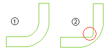
The GSM Fillet Reduction command enables you to modify a set of selected fillet surfaces by changing their curvature, while retaining the desired continuity along borders. For example, it can be used to modify some high curvature areas to let the material fill properly during stamping operation. Refer to the image of reduced fillet as shown below; the effect is exaggerated for better comprehension.
 |
1 - Normal situation |
| 2 - Fillet reduction |
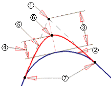
The fillet modification is done as a percentage of the continuous distance between the theoretical fillet center and its projection on the fillet surface. In order to achieve the required modification of curvature, GSM Preserving constraints are applied to maintain the specified continuity along the fillet borders, while GSM Matching constraints are built automatically to get the specified reduction ratio. A graphical explanation is provided in the image below.
 |
1 - Fillet center |
| 2 - Original Fillet |
| 3 - Projection length (L) |
| 4 - Reduction ratio (+ve) x L |
| 5 - Reduced fillet |
| 6 - GSM Matching location |
| 7 - GSM Preserving location |
After starting the command make selection for Fillet Surfaces to apply fillet reduction on them. In case you select a surface on which fillet reduction cannot be computed, a suitable warning is displayed at the time of preview.
The fillet modification is based on the value specified as the Reduction Ratio (which can vary between 0 to +1).
Additional options are available under More Options.
The Hide check box enables you to hide the original entities:
- When the check box is selected, the original entities are made hidden.
- When the check box is cleared, the original entities remain visible.
The Copy check box enables you to make a copy of the modified entities while preserving the original ones:
- When the check box is selected, the command will create a copy of the selected entities and apply the changes to the copies, without affecting the original ones. In this case, the selected surfaces can be associative or belonging to solids/skins.
- When the check box is cleared, the command will be applied on the original entities. In this case, the selected surfaces must be independent, and should neither be associative nor belong to solids/skins.
The standard GSM options like Quality Checks, Approximation, Precision and Shape Control are also available.
The options under the Preserving parameters node enable you to define the continuity that will be preserved at the borders for the fillet.
- Type - Select the type of continuity required at the borders:
- Free - No continuity is maintained
- Position - G0 continuity is maintained
- Tangency - G1 continuity is maintained
- Curvature - G2 continuity is maintained
See Continuity Types for further details on continuity.
- Roundness: - Specify the precision value to be achieved for roundness
- Position - Specify the precision value to be achieved for positional continuity
- Tangency - Specify the precision value to be achieved for tangency continuity
- Curvature - Specify the precision value to be achieved for curvature continuity
- Default - Resets all the parameters to the default values.
The options under the Matching parameters node enable you to define the values within which matching will be achieved to reach the specified reduction ratio.
- Roundness: - Specify the precision value to be achieved for roundness
- Position - Specify the precision value to be achieved for the final position of the fillet surface
- Default - Resets all the parameters to the default values.
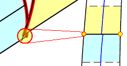
The options under the Virtual vertices node enables you to manage situations where two curves cross each other without necessarily having a real intersection at the fillet face junction.

- Type - Select the type of constraint to be applied at virtual vertices to avoid preserving constraint incompatibilities.
Refer to the Using the Virtual vertices option of the Capping command document for details.
- Tolerance - The threshold value for which the virtual intersection between the two curves is searched. When you enter a higher value, the probability to find an intersection is also higher.
Advanced options for applying fillet reduction are available under the Advanced Options node:
- Free Boundaries selector - you can optionally select those edges on which you don't want any preserving constraints to be applied.
- Surfaces without Matching Constraints selector - you can optionally select those surfaces on which you don't want any matching constraints to be applied.
- Side clearance - It is the distance from the junction of two surfaces where no fillet reduction calculations are made. It helps treating cases of not well connected surfaces, or surface with different fillet shapes that would result in incompatible GSM Matching constraints.
- Continuity tolerance - It is the maximum acceptable gap between two fillet surfaces for them to be considered for fillet reduction calculations.
- Fillet boundary continuity threshold - It is the maximum acceptable angle between two edges of the same fillet to be treated as a single edge for fillet reduction calculations.
- The Transitions at Ends check box enables you to define the variation of the deformation at the extremities from specified reduction ratio to 0.
- When the check box is selected, the transition is applied if the fillet branch length is greater than the Min. transition length and it will last till the end of the branch or Max. transition length, which ever is reached earlier. If the fillet branch length is greater than specified Max. transition length value, the reduction ratio will become constant beyond the transition.
- When the check box is cleared, no transition is applied.

1 - Without transition; 2 - With transition; 3 - Comparative illustration
- The following options enable you to display (preview) the computed preservings, matching & virtual vertices to have a feedback on the effect of various related parameters.
| 1 |
- |
Show Matching Curves |
: |
Enables you to see the preview of curves where matching is applied. |
| 2 |
- |
Show Virtual Vertex Location |
: |
Enables you to see the locations where virtual vertices are present. |
| 3 |
- |
Show Preserving Boundaries |
: |
Enables you to see the preview of boundaries that are being preserved. |

After making all the settings, select the Preview ( ) button. The application will make the calculations (that may take some time) and display the preview of the modified surfaces. In case of issues, suitable warnings will be displayed on selecting the Show Warnings (
 ) button. If satisfied with the preview, you can apply the command.
Methodology articles related to this topic
 e-Learning on Global Modeling


 Global Shape Modeling
 Fillet Reduction


 ) button. The application will make the calculations (that may take some time) and display the preview of the modified surfaces. In case of issues, suitable warnings will be displayed on selecting the Show Warnings (
 ) button. If satisfied with the preview, you can apply the command.