As soon as a preview is displayed, you can check the results you obtained. You can:
First of all, if the Show warnings button (  ) is visible, click on it to have warnings displayed on the model (the button will change to
  ).
).

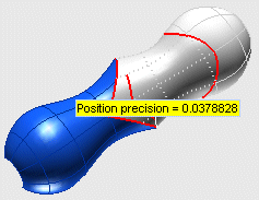
As you could see in the picture above, warnings show you exactly the parameter you can work on in order to achieve the desired result.
In the case of our example you got a warning about the precision of the positional continuity. To modify this value you will have to select Precision under More Options and change the Position value.
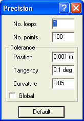
To define the precision values to be achieved during the computation, you can click the Precision under More Options to open the Precision dialog box:

inside which you can modify the following parameters:
| No. loops |
The number of iterations the programs must perform in order to achieve the desired precision. Increase this number to get a higher precision. |
| No. points |
The number of points to be used by the program in order to achieve the desired precision. Increase this number to get a higher precision. |
| Position |
The precision value to be achieved for positional continuity, in millimeters or inches, depending on the current unit of measure. It is the gap between the resulting surfaces and the constraints. |
| Tangency |
The precision value to be achieved for tangency continuity, in degrees. It is the difference between the real tangency and the one you obtained. |
| Curvature |
The precision value to be achieved for curvature continuity, as a percentage of the maximum curvature. |
| Global |
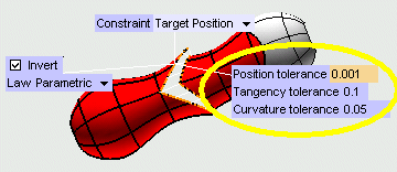
When the check box is not selected, a set of local tolerance values is attached to each group, as in the following illustration.

To hide the local precision values, select the check box. |
If a warning is displayed about some precision value, proceed as follows:
| 1 |
Increase the value of the No. loops and/or No. points parameters (or decrease the precision to be achieved, if this makes sense). |
| 2 |
Once you modified the values, click the Preview button (  ). ). |
The model will be rebuilt using the new values and a progress bar will show the completion percentage of the process. When the desired result is achieved, the  button (Show warnings) disappears.
As to how to manage precisions when rebuilding the model, see Precision management in Associative GSM.
 ) is visible, click on it to have warnings displayed on the model (the button will change to
  ).
).


 ).
).