

Modify Global Shape Modeling
 3D Bounding-Box
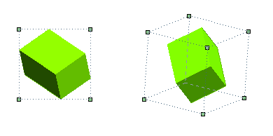
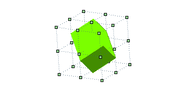
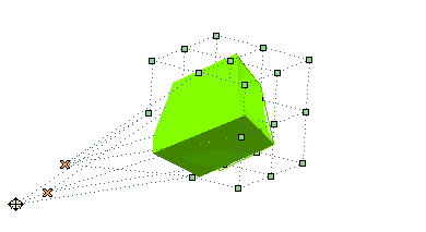
The 3D Bounding-Box command enables you to define a controlled modification using a set of vertices in the 3D space. You can proceed as follows.


Note
|
The following additional options are available under More Options.
| Copy | Enables you to choose whether to modify the original entities or to apply the changes to a copy.
|
||||||
| Snap to markers | Makes it easier to move control points by using the snap.
|
||||||
| Hide | Enables you to manage the visualization of the original entities during the editing session.
|
||||||
| Quality Checks | Using this option a set of quality check commands can be applied. See "Quality Checks" in the online documentation for further details. | ||||||
| Approximation | Enables you to convert your results to NURBS, as described in "Get NURBS surfaces instead of specialized ones" in the online documentation. | ||||||
| Tools | This node enables you to perform several operations on the selected points:
|
||||||
| Drag display | The check boxes available by expanding this node enable you to control the visibility of the cursor, control point markers and shadows during mouse drag operations. Turning the visibility off can be useful when the involved entities are complex, to better visualize the shape and the location of the curve during the operation.
|
||||||
| Minimum thickness | This option is useful only in the special case where the reference 3D grid of control points might be reduced to a plane or a line. |
| Restoring selections after an interruption If you interrupt the command, your selections and settings are not lost: they are "frozen". This way you can use the previous selection without the need of re-selecting them all over again, which might take a long time for complex situations. Next time you start the command, in fact, the Restore Selection button (  ) will be displayed on top of the selection list. If you select this button, all the selections you made and the settings you defined last time while using the command will be restored. You can now proceed without the need to repeat those selections/settings. ) will be displayed on top of the selection list. If you select this button, all the selections you made and the settings you defined last time while using the command will be restored. You can now proceed without the need to repeat those selections/settings.When the command is started with some pre-selected entities, if you select the Restore Selection button, you will be asked to confirm restoring the frozen command selections, thus resetting the current selection. |
You can freely move the selected points, thus interactively applying a controlled modification to the involved entities with instantaneous control on the result thanks to the preview mechanism.
