Please note that you can accomplish this task by loading sample file "globalplanar01.e3"
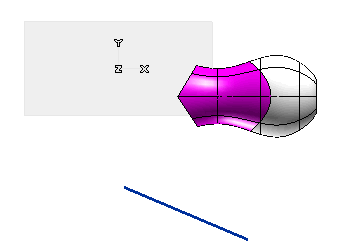
In this job you will apply a controlled modification to a surface through a set of control points by using the Planar Bounding-Box command.
Please note that you can accomplish this task by loading sample file "globalplanar01.e3"

| 1 | Define the type of entity the controlled modification is to be applied to. In the Entities drop-down list under
Entities to Be Modified you can select the type of entities the deformation is to be applied to:
|
||||
| 2 | Select the entities the controlled deformation is to be applied to: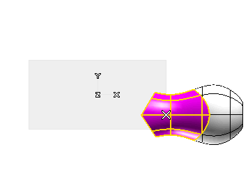 A rectangular grid of five control points along each side will be displayed : 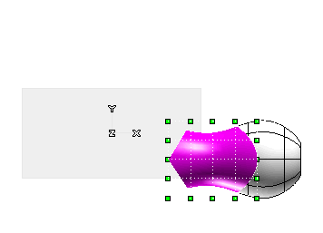 Note that you can always add points to the initial grid by proceeding as follows:
|
||||
| 3 | Define the deformation plane — that is: the plane containing the control points to be used to deform the shape — by choosing one of the items in the Mode drop-down list:
|
||||
| 4 | Apply the controlled deformation using the control points. Once the deformation plane has been selected, the deformation can be applied by setting the Mode to
Edit control points and then by selecting control points (about the selection of control points, see "
Edit Control Points") and dragging them about to the very position corresponding to the deformation you want to apply: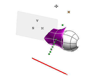 The following picture shows a different deformation applied using the Work Plane as the deformation plane (the view plane coinciding with the Work Plane): 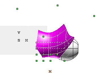
|
||||
| 5 | Click  or or  to confirm your selections modify the shape of the object, or click to confirm your selections modify the shape of the object, or click  to discard your changes. to discard your changes. |