
![]()
Modify SolidSubdivision Solid
The Subdivision Solid command enables you to modify a Subdivision solid in a number of possible manners, that is by creating features on it, moving it, creating drawing layouts of it, and so on. In addition, you can modify a Subdivision solid by editing its controlling mesh.
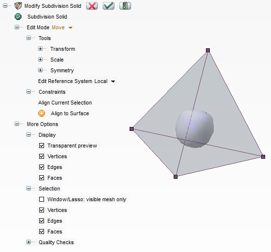
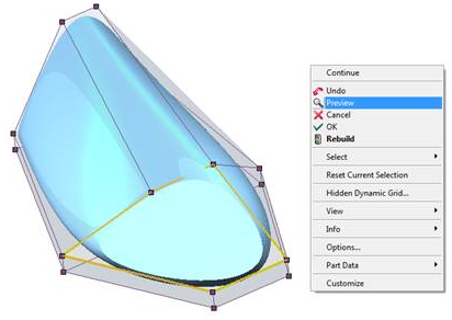
The command is based on the standard use of markers. When the mouse is placed over a face, edge or vertex, the latter is highlighted in the default thinkdesing mouse-over color (namely red). When the marker is clicked upon, it is highlighted (in orange by default) and selected. Holding the <CTRL> key and clicking on an item will deselect it if it was in the selection, otherwise it will add it to the current selection. Window and Lasso selection methodsa are also enabled. Furthermore, whenever a current selection is available, an item is added to the context menu (accessed by right-clicking anywhere in the drawing area) called Reset Current Selection, so as to enable you to empty the current selection.
Once you have selected the Subdivision solid, the associated mesh is displayed, and you can select the Edit Mode.
Split face, Remove face and Subdivide face modes enable you to perform the homonymous actions, the selection being performed directly onto the face markers.
Move: For move operations, there is only one mode in which any selected markers can:
 Input or in System OptionsInputMouse Input)
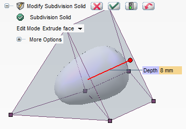
Extrude face provides you with a depth handle to control the length at which the extrusion is made. Simply select the face to extrude and the handle will appear at the default length (that which was previously used). The handle can then be dragged or the depth can be entered manually to get the desired shape. Do note that as before, if during the extrude operation two faces coincide exactly, that is their vertices match, the faces will be destroyed and the shape fused on these vertices.
Add face enables you to to add a face. It is a counterpart to the Remove face mode. If the selection of edges is valid, the standard preview button appears at the top of the selection list. When this is clicked, the corresponding face will be built and the underlying solid updated. Do note that the added face will be the smallest possible given the selection as illustrated below.
More Options
A number of useful options are available so as to make the command more effective.
This menu is shared by every mode. It contains utilities for the selection and display of markers and
a set of Quality Checks commands.
| Selection and Related Movement As for Selection and Related Movement, please take into account that pressing the <SHIFT> or <CTRL> keys will enable you — as it ordinarily is in multiple selection commands of this type — to select/deselect multiple entities respectively in a row/adjacent or freely add/subtract one or more entities to the current selection. |