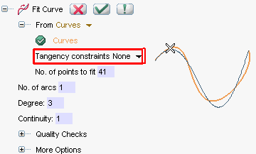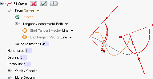
- None
to set no tangency constraints at the end points. - First
to set a tangency constraint at the first end point. - Both
to set a tangency constraint at each end point. - Second
to set a tangency constraint at the second end point.
By default, the tangency constraints at the end points will be such as to ensure coincidence between the fitting curve tangents at the end points and the ones of the original curve.
As soon as one of the above options (other than None) is selected, handles are displayed at the fitting curve end points and the
Start Tangent Vector and
End Tangent Vector drop-down lists show up in the Selection List.

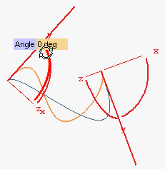
You can drag the handles in order to interactively rotate the corresponding tangent, or click on them to display the Angle mini-dialog box in which to type the value of the angle of rotation.

Alternatively, you can choose an option inside the above said Start Tangent Vector and
End Tangent Vector drop-down lists so as to align the tangents in one of the available modes (see "
How to define an axis or a line" for details).
- The Maximum distance box displays the distance of the point furthest away from the resulting curve.
- The Mean square error box displays the value of the mean square error of the curve

where di are the distances of the points to fit. - Select the Control points check box to display the control points of the resulting fitting curve.
- Select the Inflection points check box to display a black square marker on each inflection point of the resulting fitting curve.
- Select the Curvature command to display a dynamic plot of the curvature of the resulting fitting curve.
- Select Most distant point to display a black square marker on the point that is furthest away from the resulting fitting curve.
- In order to recalculate the curve by iterative refinement of the solution, you can:
- Choose the type of accuracy the refinement process must achieve in the Quality drop-down list. Three levels are available ( Low, Medium, High): the less accurate the level, the quicker the process.
- Repeatedly Select Iterate. The Mean square error is reduced. You can repeat this process until its value is stationary.
- Select the Ignore some option in the Fit points drop-down list and then select some points, among the already selected ones, to be ignored when calculating the fitting curve.
- Choose the Parameterization to be used for the resulting curve:
Refined arc length the sample points are spaced as equal arc-length along the curve Current the same parameterization as the one of the curve to be fitted Uniform the sample points are equally spaced in the domain of the curve.
| Max. sampled chord error | The maximum distance between the chord (between two adjacent sample points) and the curve. Default is the ratio: Max. sampled arc length / 20. |
| Max. sampled torsion error | The maximum angle between the normals at two adjacent sample points. Default is 5 degrees. |
| Max. sampled arc length | The maximum value for the length of the chord between two adjacent sample points. Default is the length of the curve divided by the number of sample points specified. |
 or
or  to confirm your selections and create the curve.
Click
 to discard your changes.