Then set the Edit Mode drop-down list to Automatic (if not already set so).
| Filtering selection on end points You can enable the command to select points, curves and surfaces and curves or restrict selection to curves and surface curve boundaries only. A context menu is available when right-clicking on First endpoint or Second endpoint: 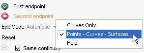
|
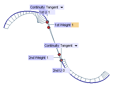
As soon as the curves are selected, the 1st U and 2nd U mini-dialog box/handle pairs are displayed on the endpoints:
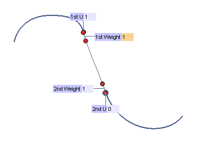
You can always change the position of the endpoints either by dragging the handles or by specifying the desired value of parameter U. You can assign a numeric value, called weight, to each of the curves to be connected so as to control the shape of the connecting curve. A handle is also available to change the weight interactively. The higher the weight, the longer the section of connecting curve that follows the shape of the connected curve starting from the point of connection. See also step 6 for further details on weights.
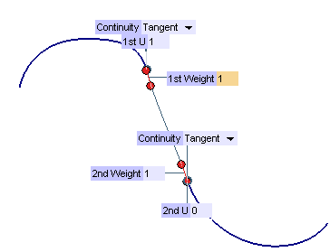
Suppose you have checked the Same continuity box. Only one drop-down list will be available in the selection list. The default value is Tangency, but you can set continuity to each of the following Continuity Types:
| Position | specifies that only geometric continuity is required at the endpoints. |
| Tangency | specifies that the blending curve must share the same tangent line as the parent curve at the given end. |
| Curvature | specifies that the blending curve must have the same value of curvature as the parent curve at the given end. |
| Torsion | specifies that the blending curve must have the same value of torsion as the parent curve at the given end. |
| Smooth curvature | specifies that the parent curve's curvature plot and the blending curve's curvature plot must be tangent continuous at the specified end. |
| Curvature plot curvature | specifies that the parent curve's curvature plot and the blending curve's curvature plot must be curvature continuous at the specified end. |
By selecting the Curve Curvature command you can also display a curvature plot which will help you check the shape and the smoothness of the resulting curve.
| Connect curve only | the only result of the command will be the connecting curve. | 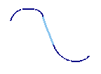 |
| Split original curves | the result of the command will be curves split from the original curves in addition to the connecting curve. These curves will join the connecting curve with the specified continuity at their ends. Thus, the maximum number of curves you will obtain with this option is three. | 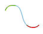 |
| Join original curves | the result will be a single curve made of the connecting curve and the two curves derived from the original ones according to the chosen endpoints and to the specified continuity conditions. | 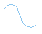 |
When Join original curves is selected, three further additional options are available:
| Max. No. arcs | specifies the maximum number of arcs (parametric spans) you want the resulting curve to be composed of. |
| Max. Degree | specifies the maximum degree to use in the resulting joined curve. |
| Tolerance | specifies the tolerance for the resulting joined curve, which is an Euclidean space tolerance for the parameter equal distance between the resulting joined curve and the original parent and blending curves. |
| Single arc | produces a single arc curve (a Bezier control point curve) with a degree determined by the specified geometric continuity conditions at the endpoints. |
| Minimum degree | produces a NURBS curve with multiple arcs. The degree — at least three — will be the minimum necessary to maintain the specified geometric continuity conditions both internally and at the endpoints. |
| Tangency | in this case weights specify the lengths of the tangent vectors: the higher the weight, the longer the section of connecting curve that follows the shape of the connected curve starting from the point of connection (about the meaning of weights, see also Significance of Tangent Weights). |
| Second Derivative | in this case weights specify the length of the second derivative in the direction of the tangent for the first and second curve respectively, which is the "speed" of the curvature change (the higher the weight, the speedier the curvature change). |
| Third Derivative | (available only if continuity is set to Torsion or higher) in this case weights specify the length of the third derivative in the direction of the tangent for the first and second curve respectively. |
| Fourth Derivative | (available only if continuity is set to Curvature plot curvature or higher) in this case weights specify the length of the fourth derivative in the direction of the tangent for the first and second curve respectively. |
| Reset When the mode is set to Automatic, the Reset button will compute the blending curve resulting from the specified geometric continuity at each end, the tangent weights at each endpoint and the setting of the Default mode (Single arc or Minimum degree). If you had previously specified curvature weights, these values will be reset to defaults and curvature weights will no longer be maintained. |
 or
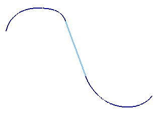
or  to confirm your selections and create the curve (s). In the following illustration you can see the curve obtained setting the Result to Connect curve only, continuity conditions to Tangency and Weight to 1 at both endpoints.
Click
 to discard your changes.