Fundamentals on Mating
 e-Learning Material: e-Learning Material:
A friendly set of e-Tutorial videos and documents on Assemblies and Mating has been created and is available on the Customer Care Corporate site (e-Learning home page). Take a look at the list of the available educational documents on Assemblies and Mating here: e-Learning: Assemblies and Mating.
Enjoy your lessons! |
This software enables you to mate objects in an absolutely natural and smart way, based on the selection of two entities in the mating objects.
This article provides you with the fundemental concepts of this topic, while further details and important operative suggestions can be found in "Mating in ThinkDesign".
The order in which you select the two entities is not mandatory, in fact the constraint that will be applied is reciprocal, thus making no difference whether you first select an entity or the other or vice-versa. The applied constraint is in fact reciprocal.
In general, then, you can work no having a "reference" entity and an entity to be positioned with respect to the one used as a reference. It's absolutely not mandatory.
In certain situations, which you can evaluate on your own, though, it might be helpful to think of the first entity as a reference and to proceed positioning the second entity with respect to the first. In case you want to really use the first entity as a reference entity, and ensure that it will really work that way, you need to make it assume an unghangeable location in the space, and to accomplish this goal you can use the Fixed constraint command. This, anyway, is a particular working method not required by the program.
In general, then all you need to do is select two entities: the constraint will be reciprocally applied to the two objects the selected entities belong to.
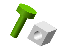
All the significant parameters are displayed in the selection list and drive your mating actions.
- As soon as the first entity is picked, the program automatically detects the mating constraint types which suit the entity you selected and you can view them in the selection list.
- Depending on the type you choose, the selection of reference entities is restricted to suitable entities only. An additional option in Mating enables you to restrict the selection of entities exclusively to Symbolic References, which can be identified anyway by a tool tip displayed by keeping the cursor for a while over them.
- You also see the preview of the object that must be positioned, while moving the cursor during the selection of the reference entity.
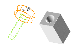
- You get additional feedback for the mating consistency, when you get close to a suitable object, and for the constraint creation. Every time the object goes over a suitable reference entities you hear a sound, see a different cursor and the preview orientation is updated to reflect the effect of the detected constraint(s). If you keep the cursor for a while over one/two suitable entities, the program displays a tool tip, describing the detected constraint(s). Similarly, you get the same information on inconsistent and existing constraints.
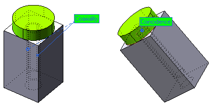
- When you click on the First entity and Second Entity and both entities are selected, the constraint is not yet created, you get the preview but to create it you need to click Apply or OK. .
- Worth remarking you can edit the constraint before clicking on the reference, that is when the constraint hasn't been created yet (always by modifying any options in the selection list), and after clicking on the reference, that is, when the mating constraint is created. You apply the mating constraint by switching to a new command, by selecting (if you chose the
Deferred mating option), or, if you wish to define a new constraint, by picking a new entity, belonging to the object that will be moved in the mating.
The program detects the suitable mating constraint types, according to the entity that you select, which belongs to the object to be moved. See the table listing the entities of the object to be positioned, on the left and the suitable mating constraints for any entity type, on the top. If you watch a specific column and a row, when the mating constraint in the column is available for the entity of the object to be positioned in the row, you see the cell at the crossing between the column and the row displayed in pale blue. Move the mouse cursor over any pale blue cell and a tool tip will display the reference entities corresponding to the specific mating constraint.
Mating provides two different constraint detection modes:
- simple — (default)
- inferred
You choose simple when you apply just one constraint a time. You choose inferred when you require the program to identify more than one constraint a time. In inferred mode, when you click on a suitable reference entity, the program creates the corresponding constraint and then tries to infer additional constraints, which are consistent with the shape of both objects, the one to be positioned and the reference one. For instance, when you mate a cylindrical pin and a blind cylindrical hole, in inferred mode, the program will add a coincidence constraint between the two planar faces that are contiguous to the pin and the hole.
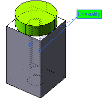
The labels that are displayed on the Graphics Area upon selecting a constraint are color coded for better understanding of their status.
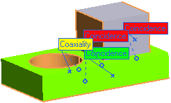
| Green |
: |
The mating constraint is consistent |
 |
| Yellow |
: |
The mating constraint is having dangling references |
 |
| Red |
: |
The mating constraint is conflicting |
 |
| Each mating label displayed in the Graphics Area will have the following attributes: |
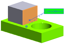 |
- A X marker is displayed over the first entity
- A O marker is displayed over the second entity
- The line pointing towards the first entity geometry is solid
- The line pointing towards the second geometry is dashed
|
While using the Coaxiality constraint, you can specify an additional alignment know as
Any. The
Any option will be internally change by the program to
Aligned or
Anti aligned depending on the constraints you apply next. This option is very useful when you are not sure of the effects that the present alignment will have on the constraints that you will be introducing later in your model.
For example, you create two constraints, a Coaxiality constraint with alignment as
Any and then a
Coincidence constraint with alignment as
Aligned, with a pre notion that the second constraint works only when the first constraint is
Anti aligned. In this case the program automatically calculates and changes the first constraint from
Any to
Anti aligned.
Note
The change of alignment from Any to
Aligned or
Anti aligned is done internally by the program. It will not be shown in the Model Structure. |
Mating enables you to drag and drop an entity partially constrained by a mating constraint to a different position. Both the preview and the final position will be consistent with the existing constraints.
A powerful tool to keep the mating constraints even after replacing a component (involved in the mating events) is using Symbolic References — identifying parametric references by means of names — with the same name both in the starting and final object. In fact, when mating solids by using Symbolic References as parametric references, the Symbolic References are stored in addition to the absolute references. As a consequence, the referenced entity can be successfully replaced by any other entity that you consider to be functionally equivalent and that you tagged with the same Symbolic Reference name.
Related Topics
 e-Learning on Assemblies and Mating
 e-Learning Material:


