Creating a capping surface starting from an existing surface
In this job you will use the Capping command to create a surface based on an existing one.
Open file "CappingExistingSurface.e3".
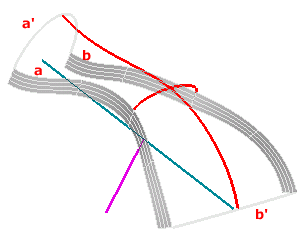
You need to create a filling surface along the two side surfaces (a and b) and the two curves (a' and b') and through the red curves, maintaining tangency continuity along the two surface boundaries.
As you can see, curvature varies strongly in both directions. Therefore, if you try to use the Capping command directly, it will not be easy to find a suitable initial shape among the predefined ones (Flat, Double curvature, Single curvature). In this case, in fact, it will be much better to create a proper reference surface and then use the Existing surface option of the Capping command.
Creating the reference surface
To create a filling surface among surface boundaries a and b and curves a' and b', adding tangency constraints along a and b, you can use the Lofted Surface command.
| 1 |
Start the Lofted Surface command. In the Type drop-down list under More Options, select Stretched.
|
| 2 |
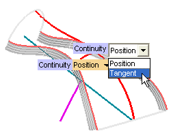
As Boundary set A, select the two surface boundaries a and b, as in the following illustration (the selection order is free). In the Continuity drop-down lists, select the Tangent option, in order to apply tangency constraints along a and b:
|
| 3 |
Select the two curves a' and b' as Boundary Set B.
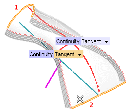
If you click the Show Warnings button, the following message shows up:
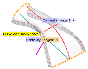
Check the Clean Curves box under More Options - Surface Type Options to get a nicer resulting surface (see "Cleaning a curve before creating a lofted surface" for details).
|
| 4 |
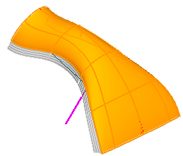
Click  to create the surface: to create the surface:
|
Creating the capping surface
The reference surface is ready, and it already fulfills the required boundary constraints. Now you are ready to create the final capping surface. So, start the Capping command.
| 1 |
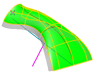
In the Generic Shape drop-down list under More Options, select Existing surface and click on the green surface.
|
| 2 |
In the Projection type drop-down list, select Single curvature, to use a cylindrical projection.
|
| 3 |
In the Axis drop-down list select Line. Click on the blue axis as in the following illustration.
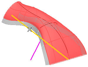
Alternatively ...
You could also set the Projection type to Flat and select the violet line as direction of projection. But, in this case, you get better results by using the cylindrical projection, as you will see further on in this task. |
|
| 4 |
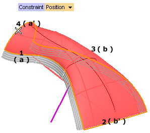
Select the four boundaries as Constraint Boundary Curves:
- Select boundary a as Group 1 and set the Constraint to Position + tangent
- Select curve b' as Group 2 and set the Constraint to Position
- Select boundary b as Group 3 and set the Constraint to Position + tangent
- Select curve a' as Group 4 and set the Constraint to Position
|
| 5 |
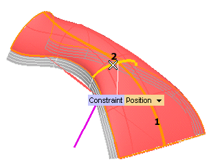
Select the two curves as Constraint Internal curves as in the following illustration, and set the Constraint to Position.
|
| 6 |
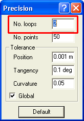
To achieve a good precision value, set the Loops to 2 in the Precision dialog box, opened by clicking Precision under More Options.
|
| 7 |
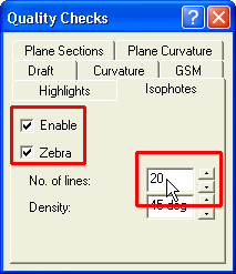
To assess the quality of the surface you are going to obtain, you can use zebra lines. Click
Quality Checks under More Options.
- Select the Enable and the Zebra check boxes
- In the Number of lines box, type 20
- Click the preview button (
 ). ).
You will get the following:
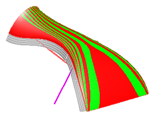
Please note that if you had chosen the Flat projection type using the violet line as the direction of projection, you would have obtained the following:
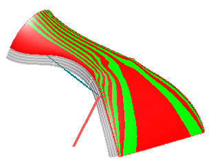
As you can see, the result obtained in the case of the Single curvature option is smoother.
|
| 8 |
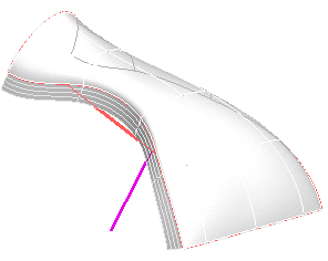
Click  to create the surface: to create the surface:
|
Tips and Tricks


 to create the surface:


 ).
).

