| Automatic |
the program automatically chooses the best type of filling surface among (portions of) a plane, a cylinder or a sphere. |
| Flat |
the surface that will be used is a portion of a plane to be defined using the Reference Plane drop-down list which shows up as soon as you select the
Flat option. For details on the plane definition method, see "
How to define a plane". |
| Single curvature |
the surface will be defined as a cylinder. You can define:
- The Axis (see "How to define an axis or a line" for details).
- The radius, by selecting the Radius check box (which shows up as soon as you click on
Axis) and typing the value into the adjacent box. The default value is displayed when you select the check box for the first time.
- The orientation of the surface, by selecting/deselecting the Invert check box, displayed as soon as you click on
Axis.
|
| Double curvature |
the surface will be defined as a sphere. You can define:
- The center.
- A Direction (see "How to define an axis or a line" for details) which can be used to define the axis between the poles of the sphere, thus defining the directions of the u and v isoparametric curves of the surface. Using this option, you can control the alignment of the isoparametric curves, avoiding undesired rotations.
- The radius, by selecting the Radius check box and typing the value into the adjacent box.
- The orientation of the surface, by selecting/deselecting the Invert check box.
|
| Saddle curvature |
the surface will be defined as a torus. You can define:
- The Axis of rotation of the torus (see "How to define an axis or a line" for details) and its
Origin.
- The Inner radius, by selecting the corresponding check box and typing the value into the adjacent box.
- The Section radius, also in this case by selecting the corresponding check box and typing the value into the adjacent box.
|
| Existing surface |
the surface that will be used is an existing one to be selected (a specific Surface item is displayed in the selection list). You will also have to select a
Projection type suitable for the surface you selected. Final results depend on the chosen projection type and on the corresponding direction. Available projection types are the following:
- Flat — a common direction of projection is used.
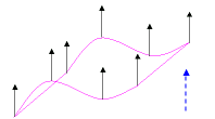
This method implies selecting the direction of projection, an Axis
- Double curvature — a spherical projection is used.
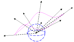
This method implies selecting the Point to be used as the center of the sphere.
- Single curvature — a cylindrical projection is used.
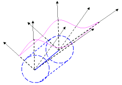
This method implies selecting the Axis(see "How to define an axis or a line" for details).
- Normal — a normal projection is used. The normal to the surface at each point of the surface defines the direction of projection.
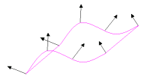
|
| 1 |
Suppose you have a set of curves like the ones in the following illustration, to be joined by a surface using the Capping command. After starting the command select all the curves using a window selection.
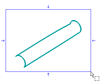
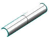
You might reasonably expect the shape of the resulting surface to be cylindrical. Once the curves have been selected, leave constraints to their default values.
|
| 2 |
Click the preview button (  ) to display a preview. The result you get is really different from the one you expected: ) to display a preview. The result you get is really different from the one you expected:
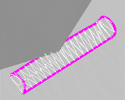
|
| 3 |
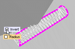
To obtain a good result, click on More Options to expand and select
Single curvature in the
Generic Shape drop-down list. Click on the
Axis item in the selection list. The
Radius and
Invert check boxes show up in the model. Select
Invert.
|
| 4 |
Click the preview button (  ) to display a preview. The result you get now is the one you expected: ) to display a preview. The result you get now is the one you expected:
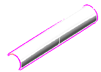
|
| 5 |
Click  or or  to confirm your selections and modify the shape of the object. to confirm your selections and modify the shape of the object.
Click  to discard your changes. to discard your changes. |


 ) to display a preview. The result you get is really different from the one you expected:


 or
or  to confirm your selections and modify the shape of the object.
 to discard your changes.