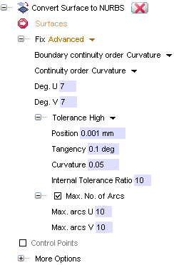
The following options are available when you select Advanced in the Fix drop-down list of the Convert to NURBS command. These settings enable you to have the maximum control on the surface continuity and precision.

| Boundary continuity order |
Enables you to select the continuity order for the boundaries of the resulting surface: Position, Tangency or Curvature. The continuity order along the boundaries is to be set as the first condition, as once it is set the internal continuity order for the selected surfaces (Continuity order, see below) is automatically set to the same degree. |
| Continuity order | Enables you to select the continuity order for the internal areas of the resulting surface. Once the continuity order along the boundaries (Boundary continuity order, see above) has been set, the internal continuity will automatically be set to the same value (Position, Tangency or Curvature, according to the choice you've made). If you select Maximum, the resulting entity will have the maximum continuity value at the internal knots, which is the entity degree minus 1 (high knot continuity, NURBS multiplicity = 1). For example if the entity degree is 7, continuity at internal knots will be 6. In general, the resulting entity will be much smoother. |
| Deg. U | Enables you to define the actual degree for the resulting surface along the direction of parameter U. |
| Deg. V | Enables you to define the actual degree for the resulting surface along the direction of parameter V. |
| Tolerance | Enables you to control the tolerance settings.
|
| Max. No. of Arcs | Enables you to control the number of arcs, affecting the accuracy of the result:
|
| Max. arcs U | Enables you to define the maximum number of arcs for the resulting surface along the direction of parameter U. |
| Max. arcs V | Enables you to define the maximum number of arcs for the resulting surface along the direction of parameter V. |
Additional settings are available under More Options. See "Using additional conversion options (More Options)" for details.