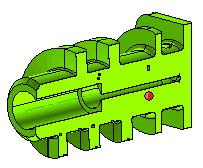
Section View Options
While using the Define Section View command, you need to define the sectioning plane in reference to a reference plane. The reference plane is defined using the
Reference Plane drop-down list of the
Define Section View selection list. There are various methods to define a reference plane as described in the
How to define a plane document.
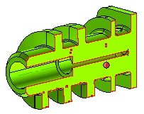
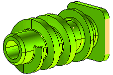
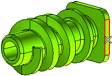
For the purpose of this document, we are using the following model for illustration with the highlighted face selected as the reference plane.
Once the reference plane has been defined, you can make use of the More Conditions drop-down list to select one of the following methods to define the sectioning plane. Depending upon the method selected additional selectors will be displayed in the selection list, their description are given under the images.
- None
The sectioning plane is created at the very same location as the reference plane.
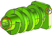
- Parallel & point
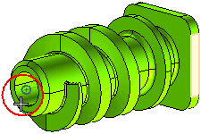
The sectioning plane is defined as the plane parallel to the reference plane and passing through a selected point.
Point: Select the point through which the sectioning plane will pass.
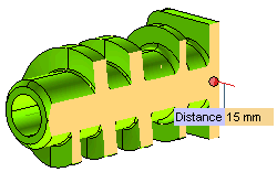
- Parallel & distance
The sectioning plane is defined in such a way that it stays parallel to the reference plane and positioned at an offset distance specified in the Distance mini-dialog box.
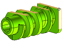
- Perpendicular & axis
The sectioning plane is define is such way that it is perpendicular to the reference plane, orients itself in the direction defined by a selected axis and positions itself on a selected origin.
Axis: Select an axis to define the orientation of the sectioning plane.
Origin: Select a point through which the sectioning plane will pass.
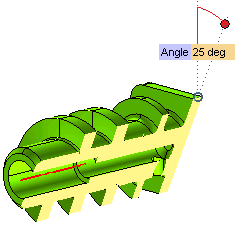
- Angle & axis
The sectioning plane is defined in such a way that orients itself in the direction defined by a selected axis, positions itself on a selected origin and subtends an angle defined in the Angle mini-dialog box.
Axis: Select an axis to define the orientation of the sectioning plane.
Origin: Select a point through which the sectioning plane will pass.
Once the section plane has been defined you can make use of additional options in More Options. The following are the options available.
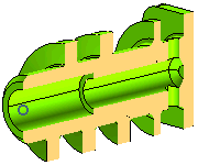
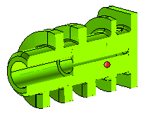
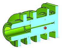
- Show Capping check box: When selected, a capping surface is displayed at the location where the material is present in the model but has been cut to display the section view. There are two options available for selection in the drop down list.
- Entity color: The color of the capping surface will be same as that of the model.
- Color: You can select the color of the capping surface using the
Color dialog box.
- Show section edges check box: When selected, the section edges of the sectioned model are highlighted.
There are two options available for selection in the drop down list.
- Rendering mode color: The color of the edges is same as that of the color of the model.
- Color: You can select the color of the edges highlighted using the
Color dialog box.
