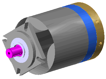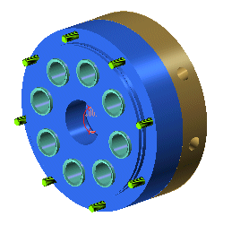
Some of the components of the above assembly are Unloaded and some are in Light Representation mode for this task and saved as a new file Pump_exp_view.e3. The effective set of components we use for this example is shown below.

The Explode Assembly command in the program has enhancements that allow designers to communicate information on assemblies much more effectively. We take the example of a sub assembly of a Hydraulic gear pump for exploring the functionalities available. The Pump assembly file Assy_pump.e3 is available in the Sample folder of your think3 application installation.

Some of the components of the above assembly are Unloaded and some are in Light Representation mode for this task and saved as a new file Pump_exp_view.e3. The effective set of components we use for this example is shown below.

| 1 | Open the file Pump_exp_view.e3
|
|||
| 2 | The Path lines enable very clear depiction of the assembly sequence of components and give you better control on the exploded view that is generated. Let's see how it works.
Continue the Explode Assembly command.
|
| 3 | Suppose you want to have control on the Path lines being generated, the Sketch path lines option should read Follow movements, so that your movements are captured. To check this option, you will displace only the component Sleeve from the assembly. There are 8 instances of this component. First orient your Work plane so that these components are visible neatly. Switch to Wireframe view.
|
||
| 4 | There can be situations when you prefer to have complete control on the Path lines created and not have the program generate them for you with either the Default Explosion or the Automatic mode options. In such a scenario, you can use the Path lines option in the Explosion drop down list. First you will move one of the components in the sub assembly and then check the dynamics of using this option.
|