

Tools Info
Info Analysis
 Entity Size
The Entity size command under Analysis displays the size of one or more selected entities in the X, Y and Z and Y directions relative to the World referencecoordinate system. This command can be applied to both 2D and 3D entities. It is possible to select a point cloud, one or more curves or surfaces or even a set of mixed entities including curves, surfaces, solids and points, or also 2D Drawing Views so as to display the sizes of the bounding box (a rectangle) of the selected set of entities.
| Note When you start the Entity Size command, the program prompts you to select a shape. This can be a curve, a surface or a set of points or any other entity. Depending upon the entity you selected (2D or 3D) the program will display a bounding box for the entity in 2D or 3D. The Along Work Plane check-box enables you to compute the bounding-box in the X, Y and Z directions relative to the current Work Plane. When not selected, the bounding-box is computed in the X, Y and Z directions relative to the World reference system. |
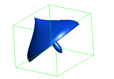
When you select an entity, at a bounding box appears over it. The dimensions of the box is such that it can just cover the selected entity. The mini dialog boxes will show the length of its edges along the X, Y and Z and Y directions of the World referencecoordinate system. In case of 2D entities the program will display a bounding rectangle.
The Along Work Plane check-box is available in the selection list.
When selected, it allows to compute the bounding-box in the X, Y and Z directions relative to the current Work Plane. When not selected, the bounding-box is computed in the X, Y and Z directions relative to the World reference system.
The program allows you to retain the bounding box obtained as a result of running the command. This will be useful when you don't want the bounding box to disappear after exiting from the command. To do so, select the Insert Geometric Data check box and apply.
When you select the Insert Geometric Data check box, you can select the Type of the bounding box for the selected entity. From Type drop-down list select the type of the bounding box you want. Depending upon the entity you have selected, the following are the types of the box:
Consider that you need to retain the bounding box as connected lines; select
the Insert Geometric Data check box, select
Lines from the
Type drop-down list and click apply.
You can individually select the lines of the resulting box, if you wish to do so.

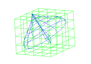
The following image illustrates the condition when Planes is selected from the list. Note that the wireframe view is used for easy recognition.

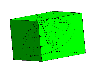
When Solid is selected from the list:

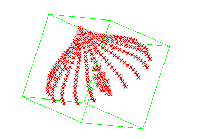
When an ascii point cloud file (*.pt) is opened in the program, you can display the bounding box for the selected points using
the Entity Size command. This can be a very useful design aid.
