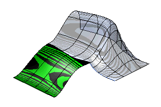
The Zebra command enables you to temporarily draw zebra lines on one or more surfaces in order to get a simplified representation of them and assess their shape. This type of surface analysis provides designers the ability to inspect a model surface for face to face continuity. If zebra lines "look good" the shape of the surfaces can be considered acceptable (that is "smooth enough"), otherwise you may want to change them.
In fact, a simple way to visualize smoothness is to use standard lighting and shading. Zebra lines can be used to:
- Detect small surface imperfections, as they reflect the variation of the surface normals
- Detect surface discontinuities, as their continuity is generally one degree lower than the one of the surface.
You can proceed as follows.
- To display zebra lines on surfaces first select the surfaces to be assessed. After selecting the first surface the Surfaces item will turn to green, but you can add any other surface to your selection going on picking them in the model.
- In the Type drop-down list you can choose the type of zebra lines to be displayed on the model:
| Isophotes |
When this option is selected, Zebra lines will be displayed as lines of constant illumination on the selected surfaces. You can select the direction of the isophote lines in the Isophote Direction drop-down list. See "
How to Define an Axis or a Line" for details on how to define the direction.
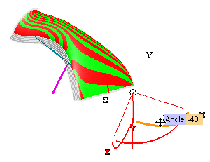
Alternatively, you can use the 3D-handle that shows up in the right-bottom corner to define the direction of isophotes/zebra lines interactively.
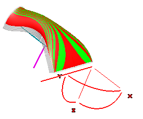
You can rotate the direction about each of its axes (one at a time) just by dragging the corresponding handle (the one marked with X, Y, or Z), or click on the handle and supply the rotation Angle value.
|
| Reflection |
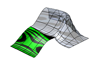
Zebra lines are displayed as the reflection lines of a black and white striped spherical texture surrounding the model and projected onto the selected surfaces. The sphere is fixed in the space and does not move when you rotate your model, so as to help you easily assess your shapes. In the Orientation drop-down list you can choose whether stripes (and thus zebra lines) must be
Horizontal or
Vertical.
 |
You can control the visualization of both types of zebra lines by setting the following parameters:
- The default number of displayed lines is 41. To modify the number of lines, change the No. of lines: value. The new lines will immediately be drawn.
- The Color. When you click on
Color, the system color palette dialog box will show up. Select a color in the palette: it will be immediately used.
- You can also change the Density: of isophotes/zebra lines. Density is an angular value:
- When you decrease the density value lines will be more "concentrated"
- When you increase the density value lines will be distributed on a wider area.
- Density values vary in the range [0-90] (bigger values are converted modulo 90).
- The Antialiasing check box controls the aliasing of the stripes.
- When the box is cleared, no anti-aliasing is activated. The transition between black and white zones in case of discontinuity will be much more evident.
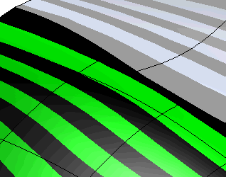
- When the box is checked, a sort of anti-aliasing mechanism is activated, zebra lines will look smoother. On the other hand, transitions between black and white zones, in case of discontinuity, will be less evident.
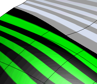
Please take into account that the quality of previews is also affected by the
Tessellation parameters: option (in the
Graphics-
Advanced category of the
System Options).
Related Topics


 Info
Info Zebra
Zebra


