Applying a shape compensation using Compensator
In the following step-by-step example you will use Compensator and the GSM functionalities in order to apply a shape compensation to a model (Courtesy of Atlas Tool Inc., 29880 Groesbeck Highway Roseville, MI 48066-1925).
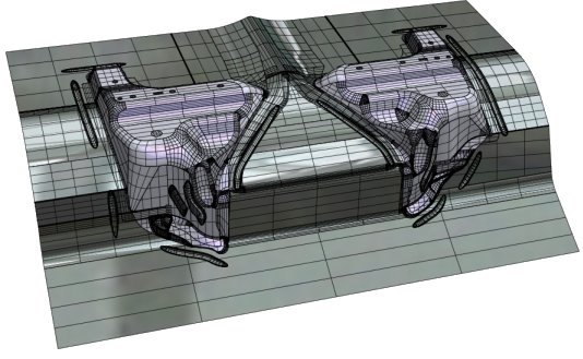
Courtesy of Atlas Tool Inc., 29880 Groesbeck Highway Roseville, MI 48066-1925
After converting the nominal and the compensated mesh file from the F.E.A. tool to the ".pt" format, you will interactively assess the result of the conversion and, once you state it is ok, you will compute the global field identification and automatically generate a small shape "containing" the modification to be applied to the whole model. Finally, using the Global Modeling functionalities, you will actually apply the compensation to the entire model.
- Start the Extract Points command.
- Click Browse for FEM File in the selection list. A file selection box will show up. Select the nominal mesh file to be opened and click Open to open it. In order to save it to the ".pt" format, do the following:
- Click OK (
 ) on top of the selection list.
- A file selection box shows up, proposing the ".pt" extension for the final file to be saved. Select the file and click Save.
A ".pt" ASCII file with the coordinates of the points of the nominal mesh file is created.
- Again using Extract Points and proceeding exactly the same way as you have just done for the nominal mesh file, save the compensated mesh file to the ".pt" format.
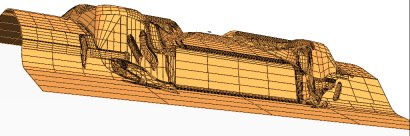
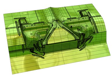
- To check the quality of the extracted points, start the Show Displacement Field command.
Click Browse for Initial Points and select the nominal ".pt" file. Do the same for the compensated ".pt" file, by clicking Browse for Target Points. Evaluate the displacement field by checking the Show displacement field box. What is being displayed are the vectors joining points in the nominal part with the corresponding ones in the compensated part.
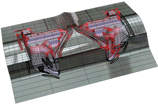
Courtesy of Atlas Tool Inc., 29880 Groesbeck Highway Roseville, MI 48066-1925
- Set the Scale to a suitable value.
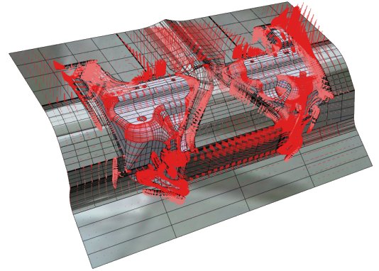
Courtesy of Atlas Tool Inc., 29880 Groesbeck Highway Roseville, MI 48066-1925
- Everything looks fine. Start the Identify Displacement Field command.
Click Browse for Initial Points and load the nominal ".pt" file, then click Browse for Target Points and load the compensated ".pt" file.
- Make sure the Tolerance value is appropriate.
- Apply the command. A message box displaying the number of loops and the minimum, maximum and mean distance values is displayed. Click OK and continue.
The small GSM surface is created.
Courtesy of Atlas Tool Inc., 29880 Groesbeck Highway Roseville, MI 48066-1925
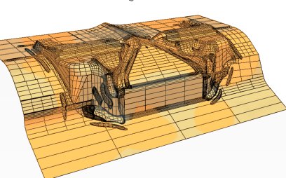
- Start the GSM Replicate command. As the Deformed reference entity select the small surface previously created.
Courtesy of Atlas Tool Inc., 29880 Groesbeck Highway Roseville, MI 48066-1925
As the Entities to Be Modified, select the whole model.
Courtesy of Atlas Tool Inc., 29880 Groesbeck Highway Roseville, MI 48066-1925
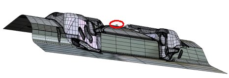
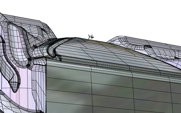
- Under More Options, clear the Hide box, in order to display also the original entities, so as to be able to appreciate the compensation (by seeing the difference between the original and the compensated shape).
Courtesy of Atlas Tool Inc., 29880 Groesbeck Highway Roseville, MI 48066-1925
You can rotate the model to better evaluate the deformation:
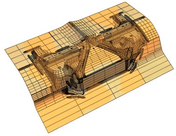
Courtesy of Atlas Tool Inc., 29880 Groesbeck Highway Roseville, MI 48066-1925
Click or  to confirm your selections.
 .
.
Courtesy of Atlas Tool Inc., 29880 Groesbeck Highway Roseville, MI 48066-1925