

Modify Compensator
 Blankholder Addendum and Part
The Blank-Holder Addendum and Part command enables you to modify the die environment based on the result obtained by the adaptation/compensation process.
During the die design process, you might have completed one or more process compensation obtaining some deformed surfaces. These deformations compensate only the Part areas of the die. The Blank-Holder Addendum and Part command enables you to change other portions of the die to accommodate the compensation result.
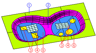
On starting the command, you need to make the following inputs in the form of solid skins, refer to the image below.
 |
||
| 1 | Blankholder | It is the area that connects the Addendum to the die sides. |
| 2 | Addendum | It is the portion of the die that has to change to accommodate the compensated parts. |
Following inputs can be made in groups. |
||
| 3 | Closing faces | It represents the holes (open areas) of the part. |
| 4 | Deformed Surface | It is the GSM surface (containing the computed transformation) obtained after applying the process compensation or adaptation. |
| 5 | Part | It is the part on which compensation/adaptation has been applied. |
To make selections under multiple groups, use the Next Group button  available besides Group. You can return to the previous group by selecting the Previous Group button. The current group number is displayed in the corresponding text box.
Using the options under the GSM options node, you can make the settings for various GSM parameters. The values of Bulge (see "An example of the Bulge factor") and of Roundness (see "An example of Roundness") can be set. Under the Precision node, you can define the various tolerance values.
Under the More Options node, following options are available:
Some results are shown below:
