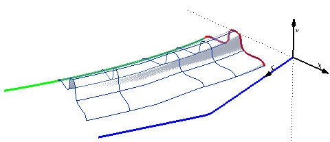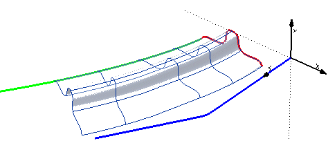
When using the Spined Surface command, you can control the way the boundary curve moves along the spine. To do this, a local reference system is attributed to the spine. The local system is initially calculated at the first endpoint of the spine curve and then moved along it. The way the local system is moved along the spine curve depends on the option selected in the Orientation drop-down list (under More Options).
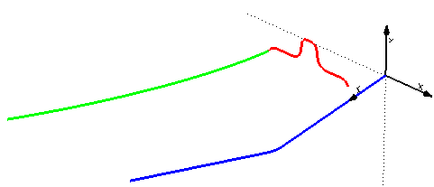
Let us see what happens in the model of the following illustration (to try it, load file "spsrf_orientation.e3"), where the blue curve is the spine, the red curve is the boundary and the green curve is the drive.

| Automatic | The X direction of the local system is determined as follows:
 |
| Defined with curves | The X direction of the local system is calculated by joining points on the spine to the corresponding points on a selected curve or curve chain (which may also be the same as the drive). Select the curve (you can change the selected curve by right-clicking on 1st Drive in the selection list and selecting
Reset in the context menu). |
| Intrinsic system | The reference system is the one defined by the spine curve. |