To change the selected surfaces (for example if you selected the wrong ones by mistake), right-click on Reference curve or surface and/or on Surface to Be Modified in the selection list, select Reset and perform selection again.
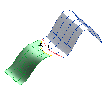
| Local | applies continuity to the entire boundary of one surface and only to the corresponding part of the other If you select this option the Approximate check box is displayed in the selection list. Select the box to approximate continuity, deselect it to have exact continuity. When the box is selected the program may try to improve the result by increasing the degree of the surface to be modified. When the box is not selected, continuity is perfect, but the surface could have some very small arc portions along the parametric direction of the involved boundary; this happens when the arc joints of the two surfaces do not correspond exactly. |
| Match boundary | applies continuity to the entire boundaries of both surfaces |
 or
or  to confirm your selections and create the surface.
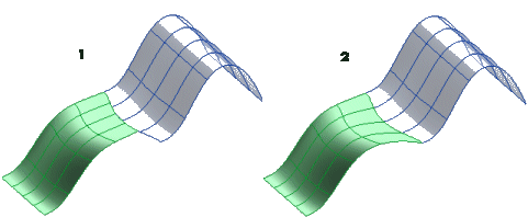
1=Result obtained selecting Local
2=Result obtained selecting Match boundary.
Click
 to discard your changes.