| 1 |
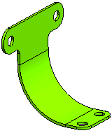
Open the step_bend.e3 file from the Samples folder of your installation. The sheet metal component contains an existing bend which is to be replaced by a step bend. The shading of the model is set to for better clarity.

|
| 2 |
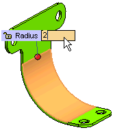
Start the command and select the bend surface from the graphics area. Expand the Local Properties branch in the selection list and specify in the graphics area the Radius value as 2. This will define the radius value of each bend in the step bend.

|
| 3 |
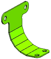
In the Number edit box of the selection list, specify 4 as the number of bends.
Note
To compute the number of bends as per the specified value of chordal error, click on the down arrow besides Number and select Chordal Error. You can now specify the value of Chordal Error in the corresponding edit box. |
|
| 4 |
In More Options, check the
Constant Angle box to maintain a constant angle between all the bends of the step bend. Finally click the
OK button  to create the step bend. to create the step bend.

If the Constant Angle check box is not selected, the angle of the last bends is not consistent with the angles of the remaining bends. |


 to create the step bend.