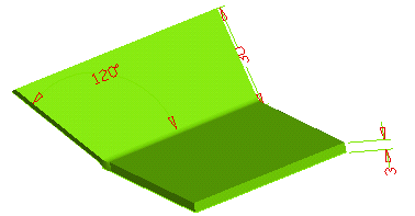
Start the Flange command. In the Length drop-down list, if not already selected, select By value.
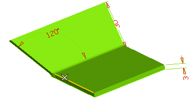
In the Length mini-dialog box which shows up, type the extension of the flange.
- Under Local Properties, in the Alignment drop-down list, select Outer flange and bend (proceed as described in "Local Properties and the Lock Marker").
- Select the Orientation check box under More Options.
- In the Reference Plane drop-down list, select Line.
Reference Plane
The Reference Plane can be defined:- As the Edge face of the selected edge.
- As the plane through the selected edge and a Line to be selected.
- As the plane through the selected edge and a line through 2 points to be specified.
- Click on the outer edge of the existing flange on the left.
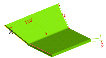
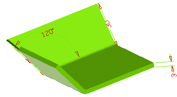
A preview is displayed:
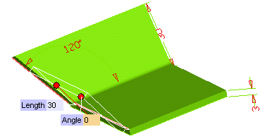
 or
or  to confirm your selections and create the flange.
Click
 to discard your changes.