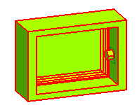
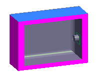
The Region Analysis command enables you to analyze and classify regions of the mold part from multiple directions. Each region will contain set of faces with different face classification.
The faces of the region can be converted to skin, which can be later used by the Region based option in the Split Mold command to create core and cavity.
On starting the Region Analysis command, the Solid selector is used to select the mold part.
The multiple direction of extraction can be selected using the Directions node.
The Invert check box enables you to reverse the selected direction.
- When selected, the specified direction is reversed to the opposite direction.
- When cleared, the direction is not inverted.
The Draft Angle edit box enables you to give a draft angle tolerance while analyzing the mold part.
The Inside box check box enables you define a boundary on the mold part to analyze the specific area of the mold part.
- When selected, it enables you to define a box area on the selected mold part. The Origin selector is used to select the center of the box and the Direction drop-down list is used to define direction of the box created. On selecting the direction, three mini-dialog boxes is displayed on the mold part. The Width size, Upward size and Depth size. You can enter the values in the corresponding mini-dialog boxes.
- When cleared, you cannot define a box area on the mold part for analysis.
The Local check box enables to view a basic and detailed analysis. It also enables you to check and change the face classifications according to your requirement.
Under the Regions node it displays the list of regions created using multiple directions. The number of faces classified under Visible (mold part) and not in the visible region are specified. The number of faces are displayed next to the color button in the selection list. The Create skins check box is used to create the skin of the Visible (mold part) faces.
The More Options give you additional functionalities for selection.
All visible directions check box: This check box enables you to view the solid with all the selected directions.
- When selected, the mold part is viewed in all the selected directions.
- When cleared, then mold part is viewed with the current direction selected under the Directions drop-down list.
Zoom entities check box: This check box enables you to zoom the mold part.
- When selected, the mold part is magnified.
- When cleared, then mold part is not magnified
Set Target Position check box: This check box enables you set a target position in the mold part.
- When selected, you can select a point as target point in the mold part.
- When cleared, you cannot set a target point
You can remove and edit the applied region analysis from the mold part. Right-click on the solid in the Model Structure and select  or from the context menu to remove or edit the region analysis respectively.
Related Topics


 MoldDesign
 Region Analysis


 Remove or Edit from the context menu to remove or edit the region analysis respectively.