You can turn the sketch into a bitmap image with a scanner and import it into the program using the Insert Image command.

There are situations in which it can be useful to import a bitmap image into a model or a drawing, so that it can be used as a reference.
Suppose the designer has created the preliminary sketch on the paper and you have this sketch as the base on which to create the real model. This may happen, for example, if the designer is far away and can't send you but a fax with a first draft.You can turn the sketch into a bitmap image with a scanner and import it into the program using the Insert Image command.

You can profitably import images into drawings, for example to customize title blocks.
Recognized image file formats are:
| .bmp | BMP format (Windows Bitmap) |
| .tif | TIFF format (Tagged Image File) |
| .gif | GIF format (CompuServe Graphics Interchange) |
| .jpg | JPEG format (Joint Photographic Expert Group - SA/CCITT) |
| .png | PNG format (Portable Network Graphics) |
Once the file is selected :
the image is placed with its lower-left corner on the origin.
the image is placed onto the current Work Plane, its lower-left corner coincident with the Work Plane origin.
A set of Options is available to enable you to control the image colors and the resize quality to be used when importing it into the model
drawing. These options can be very useful especially when the image to be imported is a big one and contains many colors.
Some editing operations slightly differ depending on the environment you're working in:
Some other operations are the same in both environments:
In the Model environment, if you move the Work Plane after loading an image, the image will remain in its original position. To move it onto the new Work Plane, use the Move to Work Plane command.
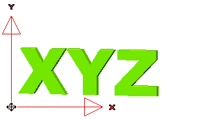
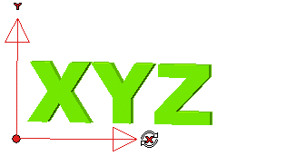
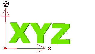
You can translate, rotate and resize the image on the Work Plane using the Edit command. An anchor handle consisting of an origin and two axes will be displayed in the lower-left corner of the image, and a circular marker in the higher-right corner.


| Note
If an image is inserted into a constrained view, it will be oriented along the view plane rather than along the Work Plane, thus enabling you to easily load three different standard views of the object (top, front, right) into the model. |
In the Drawing environment, you can translate and resize the image using the Edit command. An anchor handle consisting of an origin and two axes will be displayed in the lower-left corner of the image, and a circular marker in the higher-right corner.

