Representation of Multiple Resulting Events (MRE) inside the Model Structure
If an event is capable of generating more than one entity as a result of its application, it is said to be a Multiple Resulting Event, MRE. For example, the application of any transformation command, say Edit Move/Copy. The use of the
Copies option in this command is an event that will result in creating more than one entity from a single source entity. Consider that when an entity is "copied" more than one entity generated after that single action, the "copy". Other examples of MRE are also available in abundance, such as the
Associative application of isoparametric curves or boundary curves.
Note
Note that the term MRE is interchangeably used in a similar context. MRE is sometimes referred to as Multiple Resulting "Entities". In such situations, the stress is on the "entities that resulted" or "resultants", rather than the "events that generated them". Note that the idea is to stress on either an action or the result of that action.
|
The Multiple Resulting Entities are displayed using the icons of the commands, that created the resultants. For example, consider the application of Solid Pattern command.
In this example, a rectangular solid (Solid 2 in Model Structure, shown below) has been patterned, resulting in 4 resultant solids.

The resultant solids are grouped under Solids 3, with the icon:

This indicates that the entity is a collection of solids, which are made from repeating the Solid 2 four times.
Also the icon of the Solid Pattern command indicates that it was used to create the solid. This fact is explicitly stressed again in the
Model Structure as:

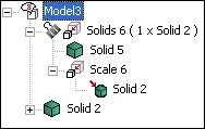
Similarly for other commands leading to an MRE, the icons will show the relation precisely. See the image below for the Edit Scale command with the
Copies option selected:
In case of transformation commands without the Copies option selected (
Edit Move/Copy,
Edit
 Mirror, and
Edit
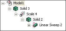
 Scale), the representation will be similar to that of GSM representations. The following image describes this behavior, when
Edit
 Scale is applied without
Copies option selected.
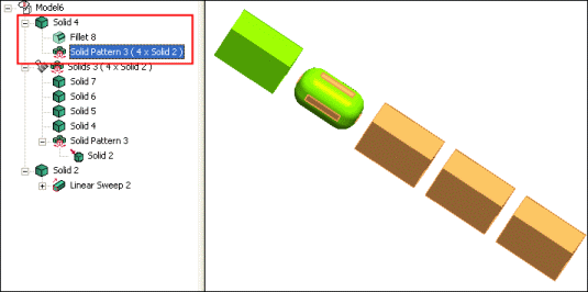
If to the resultants of a particular MRE, some features are added, the representation in the Model Structure will clearly summarize the changes. For example, in the previous example if a fillet is added to a resultant solid, in the
Model Structure it is highlighted as shown:
If all the resultants of MRE are solids and then they are applied with any
Boolean operation, the
Model Structure no longer shows the MRE representation. Otherwise, if only a few resultants are used in the Booleans, they are shown in the
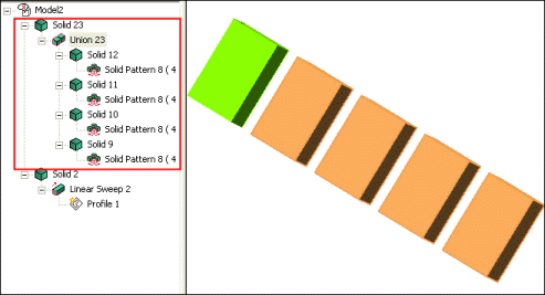
Model Structure as grayed out. For example, consider the following images showing the
Solid Union command being applied on the previous example of MRE. In image 1, all the resultants are used for solid union, so the
Model Structure no longer shows the MRE representation node. In the image 2, only 2 of the resultants are used for solid union so, they are shown as grayed out in the
Model Structure.
Image 1
|
Image 2
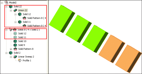
|
Tracing references
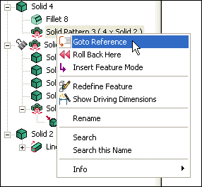
In the case of MREs, it is possible to go to a particular entity that has triggered the MRE. Right-click on the MRE on the Model Structure and select
Go to Reference, the reference entity will be highlighted.
Related Topics
 Move/Copy. The use of the
Copies option in this command is an event that will result in creating more than one entity from a single source entity. Consider that when an entity is "copied" more than one entity generated after that single action, the "copy". Other examples of MRE are also available in abundance, such as the
Associative application of isoparametric curves or boundary curves.


