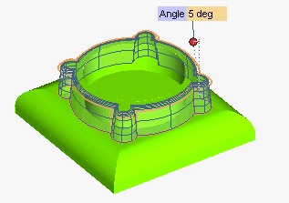
Applying a draft angle to some faces of a static solid

In this job you will apply a draft angle a posteriori to a static solid.

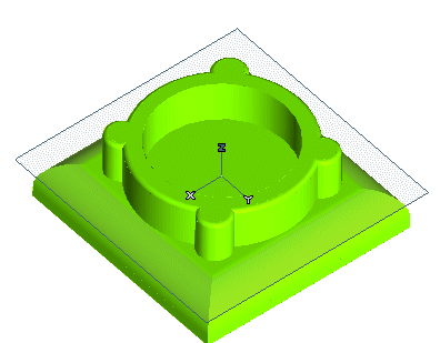
1 Suppose you have a model like the one in the following illustration. For example, it might be a static solid imported into the think3 application from another environment.


Start the Zone Draft command. You will add a draft angle about the Z axis to the side faces of the upper protrusion.
2 In the Direction drop-down list, select Z.

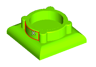
3 Select the faces the draft angle must be applied to. First, click on one of them.


The Chain check box shows up, as the currently selected faces have tangency continuity with others faces in the same solid
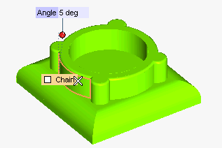


  • When the check box is not selected selection includes only the actually selected faces.
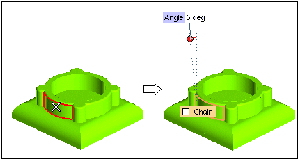


  • When the check box is selected, selection includes all the faces having tangency continuity with the actually selected ones.
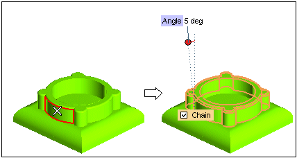
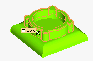


Now select the Chain check box: all the faces with tangency continuity are automatically selected.


The draft angle must not be applied to the top face, so:
  • Uncheck the Chain box
  • Press the CTRL key and contemporarily click on the top face to deselect it.
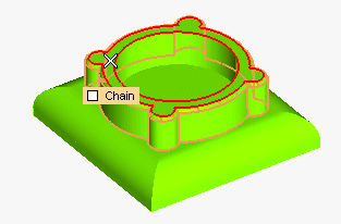


The top face has been deselected. All the faces the draft angle must be applied to are now selected (and no others).
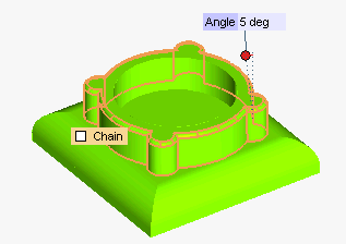


4 In the Angle mini-dialog box, type the value of the draft angle to be applied.

Choosing the drafting method
The Draft constraint drop-down list enables you to choose two different drafting methods:
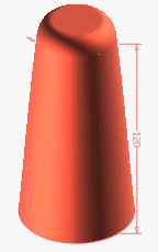
  • Strong — when this method is selected, the applied draft will be closer to the specified angle along the whole extension of the selected entities. This option is more suitable for mechanical parts.
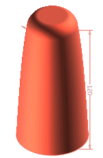
  • Weak — when this option is selected, the applied draft will be close to the specified angle near the fixed boundaries and looser as you move farther from them. This option is more suitable for industrial design.
In the following illustrations you can see the different results obtained by applying the command using the two options on a model for which the difference is particularly evident.

Strong Weak


5 Click the Preview button ( ) to display a preview of the result.


To check the precision values you obtained, you can click the Show Warnings button ( ). You can check the results you obtained as described in "Checking your results".

6 Click or to confirm your selections and modify the shape of the object.
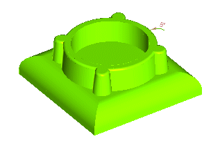


Click to discard your changes.
While you are using the command, you can select the Hide check box to temporarily hide the original entities, in order to better appreciate the changes you are making. The entities will be hidden only as long as the command is being executed.
Gap between the modified surfaces and the other ones
If, after the modification, the gap between the modified surfaces and the other ones is not negligible, a message is displayed when you try to apply the command (using Apply ) or OK ( ) to let you know that, though the solid can be created as it is, keeping such a big gap value might cause troubles in future developments.
The set of options provided to manage the shape of the controlled modification (stiffness, roundness, bulging) and especially the ones affecting precision) can be used to reduce the gap to an acceptable value.

Tips and Tricks