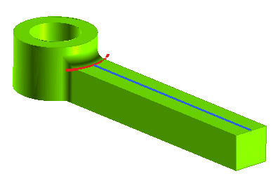
Start the GSM Bend command and select the solid.
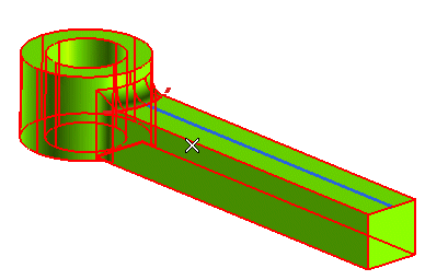
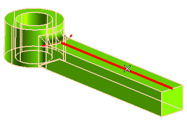
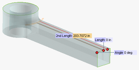
The handles show up.
 or
or  to confirm your selections modify the shape of the object.
Click
 to discard your changes.
In the following step-by-step example you will use the Use limiting curve option of the GSM Bend command to bend a portion of a solid limited by a curve.
| 1 | Load file "GB_LimitingCurve.e3". Start the GSM Bend command and select the solid. 
|
| 2 | Under More Options, select the Copy check box. |
| 3 | Select the bend line.

|
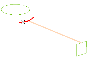
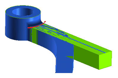
| 4 | Under More Options, select the Use limiting curve check box. Then select the red curve as in the following illustration.
 The handles show up. 
|
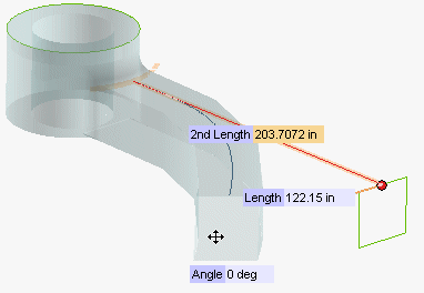
| 5 | Drag the Length handle to the desired position or type in the corresponding value.

|
| 6 | Click  or or  to confirm your selections modify the shape of the object. to confirm your selections modify the shape of the object. Click  to discard your changes. to discard your changes. |