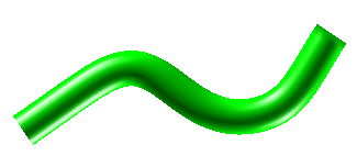
In this task you will bend a surface and change its continuity conditions at the end points of the bending line. You will appreciate how changes are propagated throughout the surface, beyond the area covered by the bending line. To accomplish this task, open file "bend_continuity.e3".

| 1 | Preselect the surface (see also Selection and Preselection).
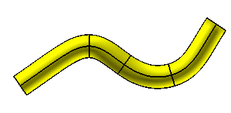 Start the GSM Bend command. To create a solid which will retain an associativity link to its base entities, so that if you modify such entities the solid will be updated accordingly, select the Associative Mode check box. In this task, the Associative Mode check box has not been selected. |
| 2 | To define the bend line, select 2 Points in the Bend line drop-down list.
Click on the two points as shown in the following illustration:
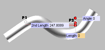 Three handles are displayed.
|
| 3 |
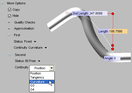
Set constraints at the first end point of the bending line. First of all, click More Options to expand it. Under First:
|
| 4 | Drag the handle of the polar axis to the new position (or set the Length value).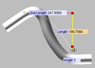
|
| 5 | Set constraints at the second end point of the bending line. Under Second:
|
| 6 | Click  or or  to confirm your selections modify the shape of the object. to confirm your selections modify the shape of the object.
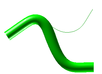 If you set the Copy option, you will obtain the following: 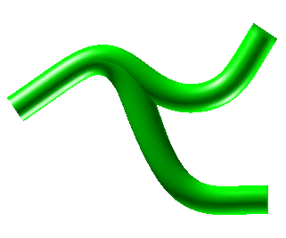 Click  to discard your changes. to discard your changes. |