
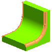
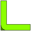
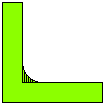
Fillets are provided on the points and lines experiencing high stress to increase the load bearing capacity and to reduce the stress concentration in mechanical parts. Fillets are also used in aerodynamics to reduce the interference drag. The think3 application provides you with four types of fillet commands:
| Structural fillets | The fillets that are responsible for the shape of the model are called structural fillets. |  |
| Finish fillets | The fillets that can be created in the later stages of the modeling without affecting the prime geometry of the model are called finish fillet. |  |
| Convex fillets | In this case, the material is removed from the edge to create the fillet. |  |
| Concave fillet | In this case, material is added to the edge to create the fillet. |  |
Fillets maintain continuity with its adjecent faces, depending upon the setting made during the application of the fillet commands. Click here to know about various continuity types.
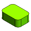
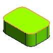
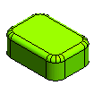
Structural fillets have been created in the first image shown below. Later on, you can be able to create the finish fillets by using the Tangency Chain option of the Edge Fillet command, as shown in images below. Also, a proper capping surface is created.
 |
 |
 |
 |
 |
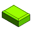
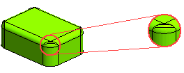
On the other hand, if you invert the order for creating the fillets, that is, if you create the finish fillets first and then the structural fillets, the right type of capping surface might not be created, as shown in the images.
 |
 |
 |
 |
 |
In order to create a shell object with constant wall thickness, it is advisable to have the structural fillets created before the Shell feature. In that case, the fillet radius of inside edges is automatically adjusted in such a way that the resultant wall thickness will be constant throughout. An example is shown in the following image.
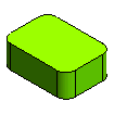 |
 |
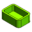 |
On the contrary, if you first create Shell feature and then Fillet feature, the result will be different. The model does not maintain a constant wall thickness, as shown in the images below.
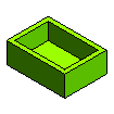 |
 |
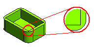 |
It is always advisable to create the Draft feature before the fillets in a model. In the following set of images, Draft feature has been created first and then Fillets have been made, that have constant radius.
 |
 |
 |
On the other hand if draft is provided on the filleted model, the resulting fillets will be tapered or have variable radius, as shown in the images below. This might not be the designer's intention.
 |
 |
 |
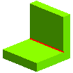
Always provide big radius fillets before smaller ones. As you can see in the images below, bigger radius fillet has been created first on the selected edge and the fillet of small radius has been created later.
 |
 |
 |
 |
 |
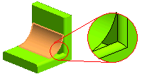
On the contrary, if you invert the sequence of creating the fillets, as shown in the images below, the capping surfaces is not correctly generated causing a defect in the model.
 |
 |
 |
 |
 |