| 1 |
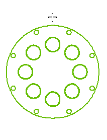
When you start the Define on Drawing command, the program displays a selection list and prompts you to specify the starting point of the line.
(Note: The selected view is automatically Set as Current by the application).
|
| 2 |
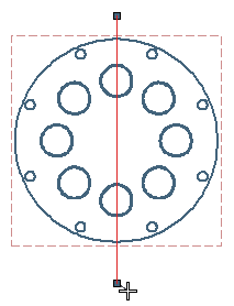
Click to specify the starting point of the cutting plane line.
From the Orientation drop-down list, choose the mode to orient the section line:
- Free — to create the cutting plane line at any angle
- HV — to create the cutting plane line aligned horizontally or vertically

|
| 3 |
The program continues to prompt for the endpoint of the line, so that you can create a cutting plane line with more than one segment.
When you have finished defining the cutting plane line, click  or or  from the selection list or context menu (right-click in the graphics area) to confirm your selections and actually create the cutting plane line. from the selection list or context menu (right-click in the graphics area) to confirm your selections and actually create the cutting plane line.
You can also access contextual options when the command is active.

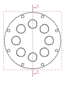
The program immediately draws the cutting plane line.

If the cutting plane arrows are pointing in the wrong direction, you can reverse them by using the Invert command.
|

 or
or  from the selection list or context menu (right-click in the graphics area) to confirm your selections and actually create the cutting plane line.

 Non-sectionable views