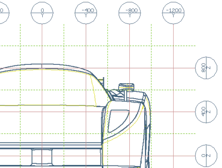
The Reference Grid command enables you to create a reference grid and position it in a two-dimensional drawing view.
This command is capable of easily and interactively referring each detail of a drawing to a reference coordinate system is very useful in many design fields.
The reference grid is a set of lines and labels.
Behavior of the command:
- The axes of the reference grid depend on the view direction: an axis of the grid is displayed on a certain view only if it is normal to the view orientation.
— Standard grid lines represent the projection on view of a plane normal to view orientation.
— Sectioned grid lines represent the projection on view of the intersection between a plane not normal to view orientation and the section plane. (This is an exception only for sectioned views).
The number of axes on a view may then vary from zero to two. In the World reference system:
- In orthogonal views (Front,
Back,
Top,
Bottom,
Left,
Right) the grid will display lines in two directions.
- In auxiliary views deriving from orthogonal the grid will generally display lines only in one direction.
- In isometric views (Right Front,
Left Front,
Right Back,
Left Back) the grid will not be created at all (because none of the three axes reference coordinate system is normal to the view orientation), so no lines will be displayed.
- In general, the number of axes depends on the number of reference planes (Front plane, Top plane, Left plane) the normal of which is perpendicular to the view direction.
- In sectioned views, reference lines on the section plane will also be displayed.
- The orientation of the grid is consistent with the view angle (useful for auxiliary and sectioned views).
- Labels at the ends of the grid lines are automatically computed and updated at any regeneration of the view.
- All entities belonging to the grid belong to a group nested inside the view icon in the Drawing Structure.
Note: This command is not available if the drawing doesn't contain any views.
Try to ...


 Dimension
 Reference Grid
 is the projection of the plane defined as the locus of points (X,Y,Z) with Z=400.
 ).
).