| 1 |
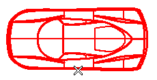
When you start the Reference Grid command, you are prompted to select a view.
You can select the view by clicking on it either in the drawing or in the Drawing Structure.
|
| 2 |
Click on the view you want to insert the Reference Grid in.
|
| 3 |
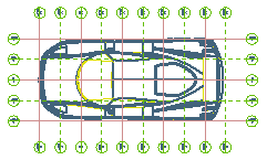
The program immediately displays a Set Boundary option, which permits two possible grid definition modes.
Select one of the grid definition mode from the drop-down list.
| Automatically |
If this mode is selected, the boundaries of the grid are automatically computed based on the bounding box of the selected view, so as to cover the whole view and extend beyond its boundaries as much as specified in the Offset box.
When you Regenerate View, grid bounds are automatically updated as to the new view bounding box.
|
| By 2 points |
If this mode is selected, you will specify two points which will define the grid extension.
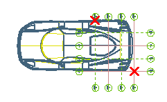
If a non-null Offset is defined, the grid will be enlarged as much as specified in both directions with respect to the bounding box determined by the two selected points.
|
|
| 4 |
In the Step box, specify the distance between two subsequent grid lines. |
| 5 |
In the Offset box, specify how much the grid is to be extended beyond the specified boundaries (both
Automatically and
By 2 points modes).
- You can reset the Set Boundary option by choosing other option from the drop-down list before the command is applied.
- You can also reset the selection list options using from the context menu of the
Drawing Structure after the command is applied.
|
|
| 6 |
Click Properties, to set or change the properties of the reference grid. |
| 7 |
Click one of the following to complete the command action: |