The Cutting Line command enables you to perform the cutting step of the metal stamping process. It computes the cutting line corresponding to the contour of the unbent wings along which the metal would be cut.
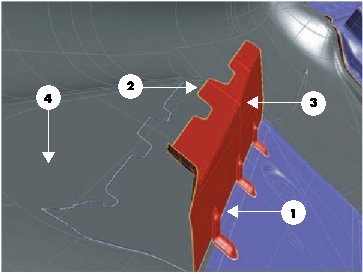 |
1 — Pivot curves
2 — Contour
3 — Base surfaces
4 — Target surfaces |
You can proceed as follows.
- First of all select the chain of curves that will be used as a pivot for the development of the curves of the wing contour (Pivot Curves).
- In the Drive Curve drop-down list, choose the drive curves to be used for the section planes.
| Pivot |
to use the pivot curves as drive curves. This choice can be useful when pivot curves do not have big curvature variations. It does not apply to cases such as the ones in the picture above. |
| Fitted pivot |
to use the result of the pivot fitting as drive curve. It can be useful in cases like the one in the picture above, when the fitting process creates a less bent curve that is therefore more regular for radial section planes. |
| Spine |
to select a spine curve (Spine) to be used as the drive curve when also the results of
Fitted pivot option are not satisfactory. |
- Then select the wing contour, that is the curves that will be developed (Contour).
- Now select the surfaces and/or faces of solids included between the pivot and the contour, that is the wings to be unbent. In the Start Entities drop-down list choose
Surfaces or
Solids and then select the corresponding entities in the model. Note that the surfaces that are the bases for the boundary curves already selected as
Contour are automatically included in the
Start Entities
Surfaces selector.
- Finally, select the target surfaces/faces of solids. In the End Entities drop-down list choose
Surfaces or
Solids and then select the corresponding entities in the model.
- The Join Curves check box enables you to determine whether the resulting cutting line will be a set of individual curves or a curve for each loop:
- When the box is checked, the cutting line is made up by joining all of the resulting curves for each resulting "loop". If only one loop is present in the resulting cutting line, then the latter will be just one curve. On the contrary, if there are more than one loop in the resulting cutting line (for instance, as in the case of "islands"), each loop will be made up of a unique curve by joining all the component curves.
- When the box is cleared, the cutting line will be made up of a set of individual curves.
- The following options are available under More Options.
| Show Section Planes |
Enables you to display or hide the section planes actually used for the computation:
- When the box is checked, section planes are displayed during the preview.
- When the box is cleared, section planes are hidden during the preview.
|
| Section Plane Percentage |
The percentage of the section planes (that are visible during the preview and are used internally to compute the trimming lines) in a comparison with the length of the pivot curves. The preview displays the trimming lines and the trimmed sectioned planes. |
| Thickness |
Enables you to define the thickness to be used when computing the allowance value.
Taking into account the values of thickness and of k-factor, metal faces undergo stretching deformations on the external metal side and contractions on the internal one, while on the neutral line the surface is supposed to remain unchanged. These deformations are empirically applied to the start surfaces, offsetting them of a value depending on the curvature of the involved surfaces so as to obtain an approximation of the same surfaces on the neutral line.
The direction where the metal thickness must be considered in order to compute the surface deformations can be controlled directly on the model through the specific arrow: you can double-click on it to invert the direction:
Inner/Outer directions
Inner direction
|
Suppose the base surface is an external metal face. Imagine to add all the thickness inside the development direction.
In this case the distance used on the end surfaces in order to compute the cutting line is equivalent to the one computed on the start surfaces after applying an offset in the internal direction which can be "t" or "T-t" depending on the curvature of the surfaces.
|
| Outer direction |
Suppose the start surface is an external metal face. Imagine to add all the thickness outside the development direction.
In this case the distance used on the end surfaces in order to compute the cutting line is equivalent to the one computed on the start surfaces after applying an offset in the external direction which can be "t" or "T-t" depending on the curvature of the surfaces.
|
|
|
| K Factor |
Enables you to define the K factor to be used when computing the allowance value. |
Restoring selections after an interruption
If you interrupt the command, your selections and settings are not lost: they are "frozen" in order to enable you to use them again without having to repeat them all, which might take a long time, at least in complex situations.
Next time you start the command, in fact, the Restore Selection button (  ) will be displayed on top of the selection list. If you select
Restore Selection button ( ), all the selections you made and the settings you defined last time you used the command will be restored, enabling you to go on with no need to repeat those selections/settings. ) will be displayed on top of the selection list. If you select
Restore Selection button ( ), all the selections you made and the settings you defined last time you used the command will be restored, enabling you to go on with no need to repeat those selections/settings.
When the command is started with some pre-selected entities, if you click the Restore Selection button you will be asked to confirm restoring the frozen command selections, thus resetting the current selection.
Further details in "Restore Selection modality for selections and settings". |
When all the selectors are green, the Preview button (  ) shows up on top of the selection list and is available to assess the result before applying the command.
Finally, note that after selecting the base surfaces, there are two possible sides where the wings could be unbent. The choice of the target surfaces and, where required, your direct interaction, will determine which side the wings will be unbent on.
- If all the target surfaces lie on just one side (A or B), then there is no ambiguity and the side is implicitly chosen.
- If some surfaces lie on one side and some on the other, a warning message is displayed to inform you the selection is indeterminate.
 |
| Select all the end entities on the same developing direction |
- If all the target surfaces lie on both sides, one side is implicitly chosen, but a Reverse developing direction check box shows up so as to enable you to invert the direction.
Try to ...

 Curve
Curve