An Overview on Large Assemblies
This document outlines the Large Assembly management.
Basic philosophy
The goal of the Large Assembly features is to let the users load, visualize and modify large assemblies composed of thousands of parts, many of which might be very complex on their own. That's why this application is designed to manage large assemblies with particular care to performance and provides end-users with two specific features designed to achieve this aim:
- Any X-Reference (component) in an assembly can be optionally loaded in a Light Representation. You can define several Light Representations for each X-Reference (component), providing different balances between simplification and visual quality; some of them can be generated automatically, some require the user's intervention. Within the assembly, you can use different Light Representations for different components, whereas all the occurrences of a specific component are opened and displayed in the same Light Representation. The same component can be loaded in its full representation in an assembly and in any Light Representation in other assemblies. When a component is opened in a Light Representation, you may get some limitations in its manipulation, depending on the kind of representation. In any case, the parametric behavior of the whole assembly is preserved: any existing parametric dependency towards that component (mating, profile references and so on) works properly, regardless of the current component representation.
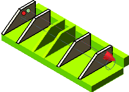
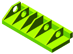
- Sometimes multiple instances of a single component are placed in an assembly and you need to create additional features only on some of the instances. However, if the original component is modified, the change will take place in all the instances. In other situations, the same component is placed in multiple assemblies and you need to create additional features on the component only in specific assemblies. To achieve both these goals, the Assembly Feature concept is useful. With this Assembly Feature concept you can add or modify placed features like holes and slots in any specific assembly. The assembly feature will be applied only in the particular assembly without affecting the original component. You will be able to create a feature simultaneously on multiple components of an assembly, as shown in the images below.
The Assembly Feature option is available in the Type: drop-down list of the Hole, Linear Slot, and Rotational Slot selection lists. This drop-down list is displayed only when you apply the Hole, Linear Slot, and Rotational Slot commands on an assembly.
See Light Representations for further information.
- One or more Visual Bookmarks can be defined for any document and, in particular, model, when you consider assemblies. A Visual Bookmark captures the general state of the model (visual appearance, feature activation status, presence or absence of Spreadsheet variables), gathering different sets of parameters which affect the amount of allocated memory and graphics resources. Using Visual Bookmarks, it is possible to specify before loading which X-Reference (component) must be unloaded, what light representation must be used for some of them, which layers are inactive and so on. And once the model is opened, the user can easily load a different Visual Bookmark any time. A Visual Bookmark can also be selected when a model is included as an X-Reference (component) into another assembly.
See Visual Bookmarks for further information.
- When trying to create 2D drawings of large assemblies, a huge amount of time is spent for generating its views. To override the time lag, you can enable the small entities filter to prevent all the entities that are smaller than a specified value from being displayed in the drawing views. This results in improving the regeneration performance of views of large assemblies containing many components too small to be seen in the drawing view.
Another use of this filter could be to initially create a draft of the simplified views quickly. Once the drawing is completed, the filter can be removed from all the views to regenerate the drawing in full detail.
During the view regeneration the diagonal (d) value of the 2D projections of each solid is compared with the value specified by the user in order to skip small entities. If the diagonal is smaller than the specified value, the solid will not be drawn in the view.
Note
The command is available on the context menu of the component in the history tree. It highlights the component in Red color in the history tree so that those components can be identified easily in the current session. This color representation is especially helpful in large assemblies having multiple components. To disable the color of the component you can select Unmark as Work in Progress from the context menu. |
 e-Learning on Assemblies and Mating


