Using the Any alignment option
The following illustration explains a situation where you will use the Any alignment option with the Coaxiality constraint for mating two components. This option is very useful when you are not sure of the effects that the present alignment will have on the constraints that you will be introducing later in your model.
Take the example of mating a Base and a Pillar as shown below. The files of these two components are available in the Samples folder of your installation location with the name Base_Any_mating.e3 and Pillar_Any_mating.e3.
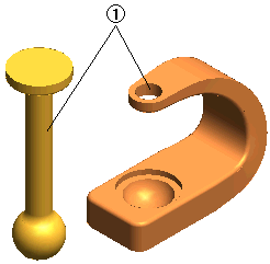 1 = Constraint - Coaxial; Alignment - Any
- Start the mating process by applying the Coaxiality constraint to the cylindrical surfaces of the Base and Pillar as shown in the above figure. While applying this constraint the Alignment: will be set to Any.
- Start with a new model file and use the (component) command to bring in the Base_Any_mating.e3 file.
- Similarly bring in the Pillar_Any_mating.e3 file.
- Choose the Mating command and select the cylindrical surface on the Pillar. Ensure that the Type: option is set to Coaxiality.
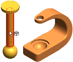
- Then select the cylindrical surface on the Base. In the Alignment: drop-down list select Any.
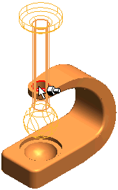
- After completing step 1, there are two possible ways to apply the second mating constraint. The first possibility is to mate the spherical end of the Pillar with the spherical cavity in the Base.
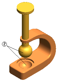 2 = Constraint - Concentric
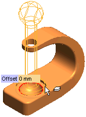
The second possiblty is to mate the cylindrical head of the Pillar with the cylindrical slot of the Base. To sucessfully carry out this mating it is necessary to reverse the alignment of the Coaxiality constraint that we applied in the previous step. The change of alignment will be done automatically by the program, as it was set to Any.
- Select the top face of the Pillar. Ensure that the Type: option is set to Coincidence.
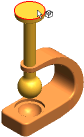
- Select the flat face of the cylindrical slot in the Base. Note that the alignment of the pillar is automatically changed to the appropriate one without any need to redifine the previous constraint.
- Finally select the Cancel
 button to terminate the Mating command.
Related Topics
 1 = Constraint - Coaxial; Alignment - Any
 1 = Constraint - Coaxial; Alignment - Any

 2 = Constraint - Concentric

 button to terminate the Mating command.