| Constant |
The local reference system and the boundary curve are simply translated along the drive curve: the boundary curve remains parallel to its initial position, although positioned along the drive curve. In this case, therefore, the boundary curve does not follow local variations in the drive curve, such as bends or twists.
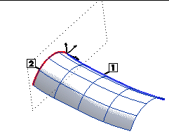
1=Drive Curve
2=Boundary Curve
|
| Curve based |
The local reference system coincides with the intrinsic system of the drive curve (defined by the tangent and the normal to the curve lying in the osculating plane — X and Y axes — and the binormal — that is, the normal to the osculating plane whose direction is such as to form a Cartesian triple following the right-hand rule — Z axis — and follows the shape of the drive curve point by point, describing its bends (points where the local reference system rotates relative to the World reference system) and twists (points where the intrinsic system rotates about one or more of its axes). The more twisted and bent the drive curve is, the more twisted and bent the resulting surface will be.
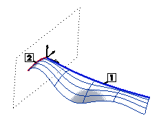 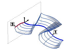
1=Drive Curve
2=Boundary Curve
|
| Along Work Plane |
The local reference system is oriented according to the Work Plane. In this case, it follows only the bends but not the twists of the drive curve because the unit vector of the X axis remains tangent to the drive curve, while the unit vector of the Y axis stays parallel to the Work Plane (for best results the latter should be well oriented; see Creating a Proportional Surface with Orientation along the Work Plane):
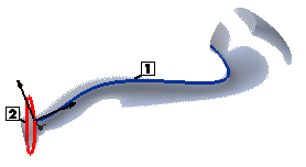
1=Drive Curve
2=Boundary Curve
Which option to choose
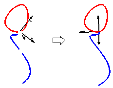
In most cases, when the drive curve is plane, the best results are obtained when the local reference system is oriented according to the drive curve (Curve based option). This orientation can also be used if the drive curve is not plane but, if the latter has marked twists in it, it is much better to set the orientation according to the Work Plane. In these cases, the best way to proceed is to set the Work Plane in such a way that it is as "parallel" as possible to the drive curve. To accomplish this, set the "midplane" through the curve as the Work Plane. In other words: select the

 command, then select the two endpoints and the midpoint of the curve.
|
|
| Surface based |
When the drive curve lies on a surface, the local reference system may be oriented according to the surface in such a way that the unit vector of its Y axis is parallel to the normal to the surface at every point on the drive curve. If you choose the surface-based option but the drive curve does not actually lie on the surface, the program projects it onto the surface. If, for any reason, the drive curve cannot be projected completely onto the surface, a message is displayed.
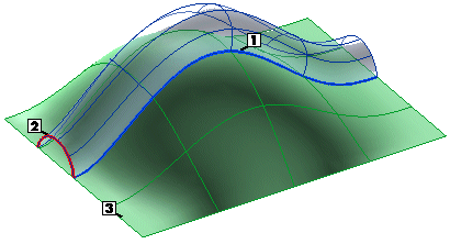
1=Drive Curve
2=Boundary Curve
3=Reference Surface
Unlike all the other cases, if the drive curve is a surface boundary or of the Curve On Surface (COS) type, no surface selection is required (the Surface selector will turn to green with the automatic selection of the surface boundary or COS support). |


 Work Plane
 Through 3 Points command, then select the two endpoints and the midpoint of the curve.
