Anchor Handle
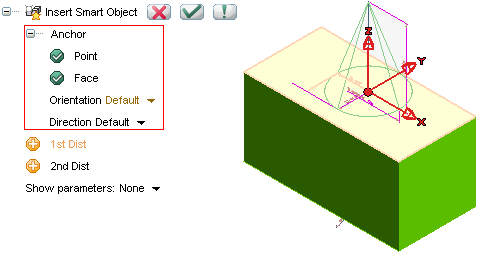
When positioning a Smart Object, an anchor point is usually to be selected: an "anchor handle" composed by an origin and three axis is displayed in this case.

Note that the selection list displays a group of items (under Anchor) enabling:
- The selection of a point (Point)
- The selection of a face (Face)
- The definition of XY plane (Orientation)
- The definition of the Z axis (Direction).
Note
- The selection of the face is always parametric: if you modify the orientation of the selected face, the orientation of the inserted Smart Object will change accordingly
- The selection of the point is never parametric, even if the point you select is parametric (a datum point or a special point of a parametric entity)
- If the origin of the base profile of the Smart Object is free (it has two freedom degrees on its plane) and the entity on which you snap while inserting the Smart Object is usable in a
Coincident constraint (a datum line, a solid edge or a line belonging to a profile), a Coincident constraint is automatically created inside the profile.
Smart Shapes and face selection
- When inserting a Smart Shape, if you move the cursor over a face, no matter whether you click on it or not, that face will be automatically selected even if you click in an empty zone of the graphics area. The orientation of the Smart Object will be changed accordingly to that face.
|
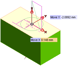
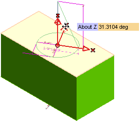
It is possible to translate the anchor by dragging the origin, to rotate each axis by dragging the related arrow, to invert one axis by double clicking on the corresponding arrow.
Each movement can be done enabling the grid (stepped input both for translation and rotation) by choosing it in the context menu.
This document describes the following:
Different types of anchors
A handle can be of one of the following two different types:
- Absolute anchor handle, if the profile or solid are not linked (for instance not positioned on a face)
- Anchor handle on face: if the profile is linked to a face (for instance if used as the base of a feature)
If the handle is absolute, also the Z-axis can be modified aligning it to some other entity. If the handle is not absolute, the Z-axis direction is automatically defined by the selected face. If the anchor handle is on face dragging is "on face" by default; in any case the Anchor unconstrained option is available in the context menu: in this case the translation will be done according to the current input mode (On view/on Work Plane/Projected on view).
Possible actions
- The handle can be translated by selecting its origin or by typing the translation values in the Move X and Move Y and Move Z (only if the anchor handle is absolute) mini-dialog boxes; the new position will be dynamically previewed. If the anchor is "on face" the point is always projected onto the face itself

- The X and Y axes can be rotated by selecting the corresponding arrow (a label is shown containing the name of the axis X/Y/Z) and dragging it or typing the angle of rotation in the About X (or Y or Z) mini-dialog box: a rotation is computed related to the cursor movement.

- If the handle is not "on face", also the Z axis can be rotated
- The Align X and Align Y options in the Orientation drop-down list enable you to align the X/Y axis by selecting an existing line or two points. When aligning this axis, the Y axis will be not movable until a new reset of the X-axis position. Only for absolute handles, Align Z is available in the Direction drop-down list.
- After using Align X (or Y), you can invert the direction of the previous alignment just by double-clicking on the X (or Y) arrow (on the Z-arrow this is possible only if the handle is absolute)
Tips on how anchors work
Whichever the type of the anchor (no matter whether absolute or on face), the behavior is the following:
- When selecting the Face, the Point is automatically defined only if it hadn't been selected before
- When selecting the Point, the Face is automatically defined only if it hadn't been selected before
- If the Anchor on face option is selected in the context menu you can display by right-clicking, the selected point, if it isn't a special snap point, is projected onto the face along the normal to the face (if any). If the face is not planar, the normal is the one through the point.
- To insert a Smart Object selecting no face (when it is optional) you have to click in an empty zone of the graphics area or, if a face is already selected, to right-click on the Face item and select Reset.
Tips and tricks


