Before starting any check action, you are recommended to incrementally save the model/drawing you are working on.
The very first checks you can perform on your document are the ones carried out by the Model Quality command (Tools Model Quality), which enables you to check the quality of a model by searching for a number of issues that may be present in the model itself and that can be of topological nature, specific issues on curves, surfaces and points or also geometric problems.
All the other check actions you can perform may require conspicuous amounts of time when performed on a big model/drawing. In order to avoid time wasting, follow the suggestions given in Checking an existing model: this way you will also work on files with very reasonable sizes.
Checking a model while you are creating it
Periodically checking the work you are doing will ensure you to get no corrupted or inconsistent data in the final model/drawing.
| Spending some minutes checking the work you are doing will let you spare a lot of time. Errors that can be easily fixed, if discovered in due time, may make you waste a lot of time if disregarded. |
Checking an existing model
When you have to check a big model, either created with the application or converted from another format, it is advisable to proceed as follows:
- Split the big model into smaller ones (for example using the command)
- Check each smaller model separately
- When splitting, mind existing relations among objects contained in the file
- If the file is an assembly file and it contains components, load and check each of them separately: this is much more effective than checking them from inside the assembly.
Sequence of check operations
It is advisable to perform the following sequence of operations in order to check your file:
- Visual check on geometric entities
This kind of check — to be performed when the current display mode is — enables you to verify the correctness of non-parametric entities like curves and surfaces:
- Surfaces or curves incorrectly described
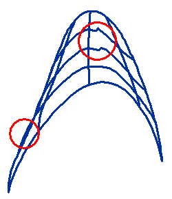 |
The surface in the illustration on the left is badly described as it shows some incorrect isoparametric curves (the ones inside the red circles). If not fixed by rebuilding the surface, this situation may cause problems when the surface will be used inside a solid. Features involving the surface may fail with no apparent reason.
Another typical case of badly described entities is the one of NURBS curves and surfaces with isolated control points exaggeratedly distant from all the others. |
- Correctness of the trimmed surfaces of the model
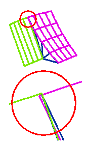 |
In the example on the left, a set of surfaces seems correctly trimmed. A more accurate analysis, which you can perform by zooming along a specific area, shows that one of the surfaces is superimposed to the others.
If you do not fix this geometric error, you may not be able to create a solid from the surfaces using the command unless you use too high tolerance values.
This error is more frequent in the areas of a model in which several surfaces share an edge or a vertex. |
- Consistency of the solid tolerance values
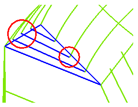 |
A simple visual check enables you to verify whether the solid has been made using a too high tolerance value. In such a case, the isoparametric curves of the surfaces seem to end slightly before or slightly after the surface edges. A solid made in such a way, although correctly managed by the application, may cause some troubles when you try to use a face or an edge in order to create a feature. |
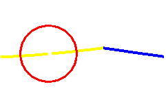 |
Another situation that might indicate a too high tolerance value is when the command does not actually trim the selected curves although they apparently intersect. |
- Entities too far away from the Work Plane origin
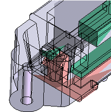 |
If, after a Fit View or a Work Plane View command or a dynamic rotation, the model unexpectedly disappears, the reason might be that some entities inside the model — like dimensions, small lines or surfaces, points — are really very far away from the origin. The only solution is to discover and delete them.
If the model is an assembly, the far entities have to be searched for inside each component, keeping into account that they might also be hidden.
The same check for far away entities must be performed when some boundaries appear unexpectedly jagged in a Shaded View. |
- Check of think3 Data Base using the command
If the database is corrupted, you might get an internal error. The only thing to do in such cases is to load the file and isolate the corrupted entities. In a lot of cases, removing the corrupted entities using the command solves the problem.
| This way, also entities that are displayed but cannot be selected are recovered. |
- Check the structure consistency for all the parametric entities
The check is possible using the Rebuild All command. This command rebuilds all the entities of the model going through all the branches of the Model Structure. If any inconsistencies are detected, a dialog box is displayed, the title of which describes the type of error that was found. See also "Recovering errors when rebuilding" for further details.
Before going on, you must solve the problem. Here are the most common:
- Failed attempt to update!
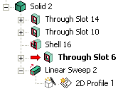 |
When a feature fails, red arrow in the Model Structure marks it. What you can do depends on the feature. Generally, the failure is due to a sudden variation of the piece geometry. If you recover geometric consistency, the error disappears. |
- Not a closed object
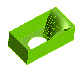 |
When you modify a parameter or a dimension, one or more faces may disappear. In the case of the illustration on the left, the too high value fillet on the top edge of a hole makes some faces disappear. If you enter a lower radius value, the problem is solved. In the application, an object is defined open only when one face ends on one or more edges.
|
- Not a manifold object
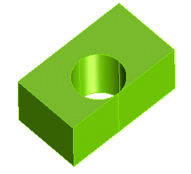 |
The solid geometrically exists, but it is not possible to build it. In the application an object is defined non-manifold when more than two faces share an edge. In the model of the illustration on the left, a hole is tangent to a face of the plate in which it was created. Three faces share the top edge of the hole: the two plane faces of the plate and the cylindrical face of the hole. |
- Multishell object!
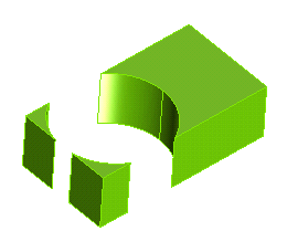 |
The solid consists of one or more separate parts. In the example of the illustration on the left, a too big hole splits into three parts the plate in which it was created. |
- Impossible convergence!
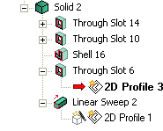 |
The trouble is in a profile inside a solid or a feature. A red arrow marks the profile in the Model Structure. Generally, you get this warning message when the profile is inconsistent or over constrained. |
- Error calculating the Work Plane
 |
You created a profile that is related to a parametric entity no more existing after you modified a driving dimension or a geometric parameter. You have to assign the profile a consistent Work Plane. For example, you can use the Redefine button of the dialog box to do so. If you recover the initial values of the modified parameters, the problem is generally solved. |
- Not consistent normals
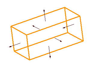 |
This problem may occur when a Boolean union is implicitly created by the command. One or more normals are incorrectly oriented. In the case of the illustration on the left, the incorrect normal is the one on the right side face. In these cases you usually solve the problem by modifying the orientation of the incorrect normal using the Check Normals command. |
If the model contains several parametric objects, you can check only the structure branch related to the selected object by using the Rebuild Object command. The error messages you get are the same as in the above list.
If the file contains components, see the note below: "A stricter check of parametric objects".
An alternative way to check the structure consistency of all parametric entities in a model is to use the and commands. You must always be able to go back and forward inside the Drawing Structure with no troubles.
Note
 |
If an event fails when rebuilding the model, a red arrow is displayed on the left of its icon in the Model Structure. If you continue with modeling process without rectifying the cause of the failure, a persistent icon  will be displayed on the failing events. It will be visible there after saving, closing and re-opening the model. This is extremely helpful in locating the events on which rebuilding failed, especially in complex models having a long Model Structure with a lot of events. The error icon disappears after the cause for the failure has been rectified. will be displayed on the failing events. It will be visible there after saving, closing and re-opening the model. This is extremely helpful in locating the events on which rebuilding failed, especially in complex models having a long Model Structure with a lot of events. The error icon disappears after the cause for the failure has been rectified. |
|
- Searching for ghost entities
After checking think3 Data Base and through the Model Structure, the last step is to verify that the model contains no ghost entities. As this kind of check will destroy your model, you will have to save it before going on.
Do the following:
- Display all layers using the command.
- Unhide all entities.
- Pre-select all entities and remove them using the command. Now, to verify if they really disappeared from the Data Base, display the layer list and check that no entities are present.
If any ghost entities are found, after reloading the original file, you can perform a selecting only the entities that are surely correct and have no corrupted data associated. Working on a file containing ghost entities can lead to Unexpected Errors. See also "Corrective actions".
A stricter check of parametric entities
A stricter check of a Model Structure can be done as follows:
- Create an empty file using the command.
- Use the command on the empty file translating and rotating it by random values, like:
Translate along X=12.45, Y=-33, Z=15.25 and also rotate about X=10.35 Y=15.15 Z=-5.73
- Using the Insert from File command, insert the model to be checked into the current empty model.
- Rebuild All.
This checking method is stricter than the one described above, as it obliges the system to compute a roto-translation of all entities. This method is particularly useful to check components that have to be positioned using the Mating command.
|
If the model gives no problems after the checking actions listed above, you may reasonably believe your file does not contain corrupted data. If you get Unexpected Errors, it must be due to other reasons. See "Error Management"
Corrective actions
As the solution to a problem is usually extremely specific, the following are only general tips.
- A good way to clean up your files — especially when the file size seems too big in a comparison with the number of visible entities — is to do the following:
- Select all the visible entities using a window selection.
- Using the command, hide all the selected entities.
- Select

 .
.
- Run the
 command.
- Run
 .
.
- Unhide the entities you had previously hidden.
This procedure removes all unexpected entities and reduces the file size. See also "Searching for ghost entities".
- If, during your visual check, you find out some curves or surfaces with a bad description or incorrectly trimmed, you can simply correct them using the proper commands, such as: Untrim Surface, Trim Surface with Limits and Split Curve or Split Surface.
| Never disregard these errors, mainly if the surfaces have to be used to make a solid. |
- If, when checking, you find out incorrect entities that you cannot recover or correct, the safest thing is to remove them using Split Surface.
- If problems are due to the Model Structure, you can try to completely or partially recover at least the geometry. You can do this for any file type (*.e2, *.e3), whichever their original format, saving the model/drawing to think3 Neutral Format (*.gkd). If, when you reload the file, some entities are no more there, this means they were corrupted and they are automatically discarded. Another way to do this is to use the Insert from File command setting the Static option (even for components).
- If you try to recover information about the structure, you will have to use the command, selecting only the entities you are sure that have no corrupted data associated. The result of this action is less reliable than the one described in previous step.
Related Topics
 Model Quality), which enables you to check the quality of a model by searching for a number of issues that may be present in the model itself and that can be of topological nature, specific issues on curves, surfaces and points or also geometric problems.


 will be displayed on the failing events. It will be visible there after saving, closing and re-opening the model. This is extremely helpful in locating the events on which rebuilding failed, especially in complex models having a long Model Structure with a lot of events. The error icon disappears after the cause for the failure has been rectified.