The visibility of the Absolute Reference System is controlled by the View
 Absolute Reference System (World) command or you can use the Shift+W shortcut key combination.
All entities present in the 3D space of the CAD environment need to have a reference to a define their location and orientation. This reference is provided by a Reference System. It incorporates an origin and associated axes to define the position of objects in space.
A reference system is nothing but a three dimensional coordinate system composing of 3 axes. The 3 axes are a set of mutually orthogonal spanning vectors extending infinitely in both directions in the space. All points or vertices in the space are then represented using a linear combination of these spanning vectors. This way they are used to determine distance and direction in relative terms with respect to their location. The think3 application makes use of three different kinds of Reference Systems:
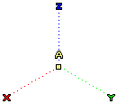
The Absolute Reference System (also called the World Reference System) is the primary reference system for the 3D / 2D environment of the think3 application. Other reference systems are based relative to the Absolute Reference System. Its position in the space remains the same at all times and cannot be modified by the user. Its axis are displayed as dotted colored lines with the alphabet A over the origin, as shown in the image below.

The visibility of the Absolute Reference System is controlled by the View Absolute Reference System (World) command or you can use the Shift+W shortcut key combination.
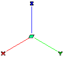
This is the active reference system associated with the Work Plane. This reference system (along with the Work Plane) can be moved freely and oriented as per requirement using the Work Plane editing commands (Edit Work Plane). The Work Plane Reference System is always positioned at the center of the Work Plane. Its axis are displayed as solid colored lines, as shown in the image below.

The visibility of the Work Plane Reference System is controlled by the View Work Plane command or you can use the W shortcut key.
The XY-plane of the Work Plane Reference System is considered as the Work Plane. Primarily, all the entities are drawn on this Work Plane and are referenced to the Work Plane Reference System.
When you enter the
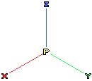
3D Profile environment, apart from the Work Plane and Absolute Reference (World) reference systems, you also have the Profile Reference System. It is represented by a P symbol at its origin, as shown in the image below.

Even though the 3D profile is always created on the Work Plane, it is at all times referenced to the Profile Reference System. On starting the 3D Profile environment, initially the Profile Reference System is placed at the same location as the Work Plane Reference System. As you progress with the creation of more entities in the 3D profile, the orientation and location of the Work Plane (and its origin) can be changed, however, the Profile Reference System will remain stationary.
The visualization of the Profile Reference System can be controlled by selecting the 3D Reference system check box in the System Options - Profile category or by pressing Y on the keyboard.
| Note
The display and appearance of the Reference Systems is controlled by the Reference Systems and Reference Systems- Appearance categories of the System Options. |