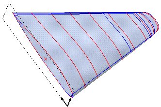
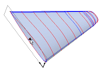
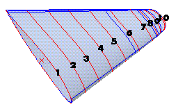
Choose Existent sections.
In order to best understand the results of this command, you should first align the Work Plane with the plane of the existing sections (the internal reference system).

Once you have done so, proceed with next step.

| Tolerance | Enables you to determine the tolerance value to be used in subsequent calculations |
| Units | Enables you to determine the unit of measurement for output |
| File name | Enables you to determine the name of the file to which you want to save the analysis results. If you omit this value, the results are shown only on screen. |
Select the standard sections
- Enables you to select the sections one by one, starting from the one nearest to the analysis point. For each section, select all the component curves, and then end selection.
Once you have selected all the sections, end the selection of the sections.

Select Layer by Layer
- Enables you to select the sections by specifying the layers on which the component curves lie (each section must consist of curves lying on a single layer, different from that of the other sections).
After defining the lowest layer and the highest layer, click OK or press the Enter key.
Cubic spline interpolation
- Select this option when the surface is very regular and the cutting planes are not "closely packed".
- Select this option when the surfaces are very irregular.
The results saved to the file appear as shown below:
Section analysis
Total number of sections 10
Section analysis results 1
Distance from analysis point 0
Section area 766.812
Analysis point (Workplane)-53.075 -0.710526
Analysis point (WORLD)-6.26495 71.5695 0
Center of gravity (Workplane)-56.3059 -0.73937 0
Center of gravity (WORLD)-9.49586 71.5406
External perimeter 197.122
Island perimeter 0
Max. length along X axis 96.6318
Max. length along Y axis 12.0791
Static moment mx -22.1183
Static moment my -2477.5
Trans. in. mom. jxg 6504.83
Long. in. mom. jyg 367635
Mom. of inertia jxx 6505.47
Mom. of inertia jyy 375640
Rotation radius xrg 2.91269
Rotation radius yrg 22.133
Polar radius polrg 22.3239
Polar moment polmi 382145
Prod. of inertia 3856.76
Center of gravity iner. prod. 3785.3
Max. center of gravity mom. 367675
Min. center of gravity mom. 6465.16
Angle of max. mom. of iner. 90.6005