The Representations command enables you to manage the 2D and 3D representations of the components in the selected catalog.
You can find this command in the context menu that displays when right-clicking on a catalog in the catalog tree frame of the Catalog Manager and in the toolbar of the command dialog box.
The purpose of creating different representations of the thinkparts catalogs, is to be able to choose the suitable one when importing the part into the model or drawing, selecting, for example, a top, side or sectioned view.
| Before creating the representations of a part, you have to create a think3 drawing for each representation with only one main view of the part. To do this, start by loading the template and create a drawing with the view you need. Do not insert notes nor title blocks. |
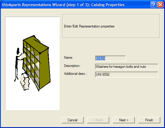
A wizard guides you in setting up the representations of the catalog with the following steps:
The dialog box displayed in the first step enables you to inspect the general catalog properties:

The buttons in the dialog box have the following functions:
| Cancel | Closes the dialog box and terminates the wizard. |
| < Back | Not enabled in this dialog box. |
| Next > | Moves on to the next dialog box. |
| Finish | Closes the dialog box and terminates the wizard. |
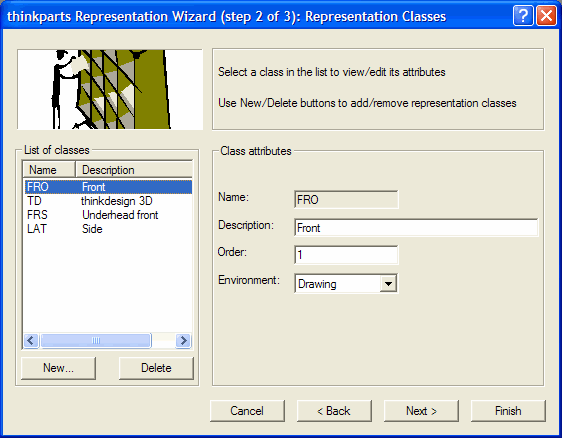
A number of representation classes can be specified for each catalog; the most common 2D classes are top, side and front views, but you are enabled to create any representation you wish. The available classes are displayed in the List of classes area, while the attributes of the selected class appear in the relevant area.

Edit the information relevant to the selected class in each field:
| Name: | The class name. This datum cannot be edited; you are enabled to Delete the class and create a New one. |
| Description: | The description of the representation class. |
| Order: | The sequence order in which the classes are listed. Press the tab key to see the effect of changes immediately. |
| Environment: | The application field of the representation class, which can be limited to a 3D Model, a 2D Drawing or All. The setting of the environment influences the choice of the template in the next step. |
The buttons in the dialog box have the following functions:
| New | Creates a new representation class. Through a small dialog box you are enabled to enter the class name; press the tab key to enable the OK button to create the class. The class attributes are filled with default values. |
| Delete | Deletes the selected representation class. |
| Cancel | Closes the dialog box and terminates the wizard. |
| < Back | Returns to the previous dialog box. |
| Next > | Moves on to the next dialog box. |
| Finish | Closes the dialog box and commits the changes made. |
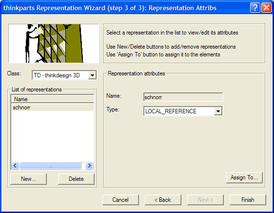
This is where you set the attributes of the representation classes defined in the previous step. For each Class listed in the pull-down menu, the dialog box displays the list of representations defined and the relevant attributes:

The buttons in the dialog box have the following functions:
| New | Creates a new representation. A standard Windows dialog box enables you to browse through your file system to identify the drawing or model that you have created for this representation (see the note at the top of this article). |
| Delete | Deletes the selected representation. |
| Parameters | Reserved for internal use only. |
| Assign To | Opens a dialog box with the list of parts in the catalog. Normally a representation is applicable to the whole of the catalog; you may, however, define a list of representations for the class, and assign them to different parts based, for example, on the dimension of the part. Simply select the parts for which you want to use the current representation, and click OK. If no part is selected, the current representation will be used for any part in the catalog. |
| Cancel | Closes the dialog box and terminates the wizard. |
| < Back | Returns to the previous dialog box. |
| Next > | Not enabled in this dialog box. |
| Finish | Closes the dialog box and commits the changes made. |