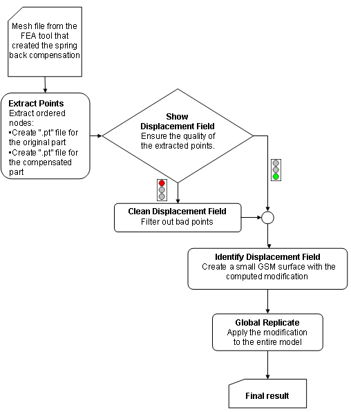
Compensator workflow for FEA Data
The Compensator process is the following:
- First of all, the mesh files obtained from the Finite Element Analysis tool that computed the spring back compensation are converted to two ".pt" files (one for the original and one for the compensated part), containing the X, Y, Z coordinates of the ordered nodes of the mesh files. This task is accomplished through the Extract Points command.
Note that the initial and target sets of points need to have "one-to-one" corresponding, that is same cardinality and order.
- The quality of the extracted points needs to be checked, which can be done through the Show Displacement Field command. The vector joining the point in the original part with the corresponding point in the compensated part is displayed. Inconsistencies across the part are also searched for.
- If any inconsistencies are detected, the bad points can be filtered out using the Clean Displacement Field command.
- The global field identification is calculated with a specified tolerance. A small GSM surface is created, which will "contain" the computed transformation. The Identify Displacement Field is used to accomplish this task.
- Finally the modification is applied to the entire model by using the GSM Replicate, that also enables you to apply only certain percentages of the transformation. Quality checks can be performed at any given percentage, so as to make sure the part does not contain any undercuts, which might turn up during the full transformation.

An example is available in "Applying a shape compensation using Compensator".
Related topics...

