

 Compensator
 Process Compensator
The Process Compensator command enables you to create the compensated shape of any process (for example, like the one required in shape distortions due to spring back effects, such as, for instance, the ones occurring in sheet metal stamping).
You can save the command session and reopen it between each F.E.M. computation. In fact, the Session drop-down list is available on top of the selection list:
| New | Enables you to start a new session. When the command ends, a session file ("target shape.xml") is created under the working folder of the command ("compensator_nn, where nn is a number automatically incremented at each session), which is located under the folder containing the "target shape.e3" file. |
| Browse | Displays a file selection box in which you can choose a previously stored ".xml" session file, which enables you to restart the command at the same saved "iteration" level. |
Once you have selected the target shape, you need to indicate a target FEM, that is a ".pt" file containing points on the target shape for iteration 0 (at the beginning of the command). It is possible to manage dense meshes in addition to light meshes computed by F.E.M. (that is, typically, the Matrix meshes in addition to Part meshes with springback).
In fact, if you click the Browse for FEM target tool item in the selection list, a file selection box will be displayed, enabling you to specify a file. The command will work on this file and will compensate it rather than the one indicated through Browse for FEM target shape.
A processed FEM ".pt" file (same name as the target, with an additional "_P" suffix), should contain the same points as the file said above, after processing. Any user supplied process procedure is accepted and enabled.
When the command is applied, an identification process is started, according to the options set under the Identification node.
| Max. Distance | The maximum distance value between two corresponding points. |
| Tolerance | The tolerance value to be reached in the identification process. |
| Max. No. of Loops | When the box is checked, you can type the maximum number of iterations to be reached in the adjacent box. When the box is cleared, the Tolerance will be taken into account instead. |
| Roundness | A roundness value. For details, see "An example of Roundness". |
| Bulge | A bulge value. For details, see "An example of the Bulge factor". |
| Optimization | By checking this box, you can activate a smoothing process for noisy data. It is also an iterative process for which you can set a maximum number of loops (Max. No. of Loops). It applies as a refinement process after the standard initial process. The result of this smoothing is that it minimizes the average distance error instead of the maximum distance error. |
| Preserving Curves | In order to manage G0 (positional) and G1 (tangency) continuity along groups of curves to be preserved, the Preserving Curves check box is also available. When the box is checked, several options are available:
|
| Symmetry | Enables you to work based on the displacement field symmetry. For details see "Computation in mirror mode". |
The compensation is computed through an iteration process enabling you to reach either the specified Same Shape Tolerance, or, if you check the Max. No. of Loops, the specified number of loops.
The Max. No. of Iterations box enables you to specify a number of iterations for the process after which the command stops, rather than reaching the Same Shape Tolerance.
The Iteration box displays the global number of iterations actually reached (therefore it is read-only and cannot be modified).
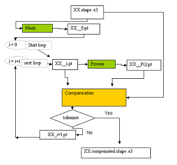
The iterations stop when the distance of the processed FEM is lower than the Same Shape Tolerance. If this value is not reached, then the command will provide the compensated ".pt" file for next iteration and run automatically the process procedure, waiting for the generation by the external process of the next "_P.pt" file.
An example is provided in the following diagram. Each time  is clicked, a working folder "\compensation_xx" is created, containing all intermediate ".pt" files. Nevertheless the initial ".pt" and "_P.pt" are overwritten during the iterations so we strongly recommend to make a backup of them. Finally, the compensated shape ("xx_compensated.e3") is saved in the same working folder.

Further options are available also under the More Options node.
| Skip message boxes | This check box controls the display of not blocking information dialog boxes allowing further processing:
|
| Approximation | Enables you to transform the final entities into NURBS. See "Getting NURBS surfaces instead of specialized ones" for details. |
| Iterations with ratio | Enables you to specify a scale factor for each stage of the deformation process. For every iteration level, the ratio can be specified in the Ratio at iteration text box. If the Max. No. of Iterations is more than 5, the inputs are split into several ranges. The required range can be selected from the Iterations drop-down list. |