The Optimize Alignment command enables you to improve the optimization of meshes, which might have been already brought closer using the Pre-Alignment commands. This tool is capable of managing correspondence defined in multiple zones, simultaneously. Hence, a set of zones of one mesh can be matched to a corresponding set of zones in the other mesh.
On starting the command you need to select the Movable Mesh and Reference Mesh. To achieve the optimization, the movable mesh is translated to match the reference mesh.
You can optionally define the zones that need to be matched. For the Limits selector, select the curves that define the boundary of the mesh zone. You need to do the same both for movable mesh and reference mesh; hence, the Limits selector is available both under Movable Mesh and Reference Mesh nodes. For each mesh, you can additionally define:
- Max. presumed distance - It is the criteria for nodes not too far from the boundary curves to define whether they are to be considered within the boundary or not. The Max. presumed distance value can be presumed as the radius of a pipe along the contour. The value should be large enough to contain several triangles (within the pipe) on each side of the contour, but not too large to avoid ambiguities.
- Min. distance - The distance of the nodes from the boundary curve should be more than the Min. Distance value to be considered for analysis. Hence, it enables you to exclude those nodes that are very close to the boundary limits.
- Invert - It enables you to define which portion of the mesh with respect to the boundary curve is to be used for the analysis.
- When the check box is selected, the portion of the mesh lying outside the boundary curve is analyzed.
- When the check box is cleared, the portion of the mesh lying within the confines of the boundary curve is analyzed.
You can repeat the above steps with another set of meshes (and its limits) by treating it as a new group. To do so, use the Next Group button  available besides Mesh Zones. You can return to the previous group by selecting the Previous Group button. The current group number is displayed in the corresponding text box. Even though you select different movable meshes in different groups, they are all treated as a single one during the alignment. Hence, the final result is always a single transformation.
Under More Options you will find the following options:
- Target Tolerance - You are enabled to enter the tolerance value within which the optimization is made. Once the target tolerance is reached, the computation process stops. However, there is no guarantee that this tolerance could actually be achieved depending on the complexity.
- Copy check box- When selected a copy of the movable mesh is retained at its original location.
- Hide check box - When selected, the movable mesh is made hidden during the display of the preview.
- Insert Transformation Reference check box - When selected, a mesh element (representing the transformation) is created, which can be used by the Replicate Alignment command to modify the position of other entities by performing on them the same controlled transformation.
- Algorithm options - The options under this node define the methodology adopted to achieve the optimization.
- No. of iterations - It enables you to enter in the maximum number of iterations (loops) allowed in the optimization process. If this number is too small, the process will stop before reaching the best possible solution. Otherwise, the process can stop before this value, if the result becomes stable.
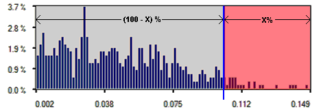
- Discarded points by distance (%) - It enables you to enter the relative distance value beyond which the mesh nodes are not included in the optimization process. This value is in reference to the specified Threshold. The system evaluates each node distance and a histogram subdivision is calculated, as shown below.

The system evaluates the cut value (blue line in the above image), defined as the distance that contains the (100-X) % of distances, and discards the X % that has distance bigger than this cut value. Hence, if the entered value is 0%, all the points are included in the optimization loop, while if it is 100%, no point is included and thus the system will not be able to make a computation.
- The Threshold is the range within which the two meshes are supposed to be matched. At each optimization loop, all the nodes of the two sets that are farther than this value are not considered in the optimization. The bigger is this value, the more are the matched points per iteration and longer is the computation time. In the Threshold drop-down list select:
- Absolute - Enter the absolute threshold value in the Threshold value text box.
- Relative - Enter the relative threshold value in the Threshold value (%) text box. It is a percentage of the maximum bounding box diagonal of movable and fixed mesh.
- Automatic - The threshold value is automatically calculated.
Note
It is not true that a bigger threshold value means a better optimization. If the two meshes are quite near, a big threshold value only increases the computation time. |
- In the Optimization mode drop-down list select the mode of mesh node correspondence to achieve optimization:
- Point to point - This method minimizes the distance between the meshes nodes. The global minimization is performed between two clouds of points. This method gives generally good result, especially in case of correctly pre-aligned objects. If the meshes represent single curvature objects the result can be shifted perpendicularly to the curvature plane.
- Point to plane - This method minimizes the distance between mesh nodes and the planes defined by other mesh nodes and normals. The minimization is performed between a cloud of points and the opposite cloud of planes. This algorithm is available only if the two sets have a support that allows the calculation of the normal vector for the points. It gives good results when the meshes represent double curvature objects that are already correctly pre-aligned.
- Global - point to point - This method minimizes the distance between the meshes nodes, using a general minimization algorithm. The global minimization is performed between two clouds of points. This method generally needs more iteration to converge, and it is slower in execution. It gives generally good result, regardless of the initial shape and the initial alignment, if provided enough iterations to run.
- Under the Advanced options node, you can define:
-
- Sampling (%) - It enables you to define the relative number of points (mesh nodes) to be used for optimization process. Before the start of the algorithm the mesh is decimated, that is, reduce the number of triangles in the mesh without any significant changes in its shape. Sampling is useful when the meshes are huge, resulting in big computation time.
- The Correspondence mode drop-down list enables you to decide how the system identifies the matching for the optimization. You can select:
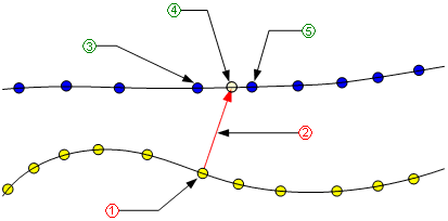
- Nearest point - This method uses a nearest neighbor search to identify the correspondence.
- Projected point - This method uses a pierce projection on the opposite set to identify the correspondence.
- Nearest projected point - This method, at first identifies the projection point and then it searches the nearest point to this in the opposite set.
 |
1 |
Guess point |
| 2 |
Guess point normal |
| 3 |
Nearest point |
| 4 |
Projected point |
| 5 |
Nearest projected point |
- Default - Selecting it will reset all the Algorithm options values to the default ones.
Related Topics


 Alignment
 Optimize Alignment
 available besides Mesh Zones. You can return to the previous group by selecting the Previous Group button. The current group number is displayed in the corresponding text box. Even though you select different movable meshes in different groups, they are all treated as a single one during the alignment. Hence, the final result is always a single transformation.
