Finally, end selection (by right-clicking and selecting Continue or by clicking on Reference Curves or Surface Boundaries).
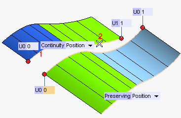
- Appropriate handles are available to move both the endpoints of the contour to be modified and the ones of the reference contour. Instead of using the handles, you can type the contour parameter value into the corresponding boxes (U0, U1).
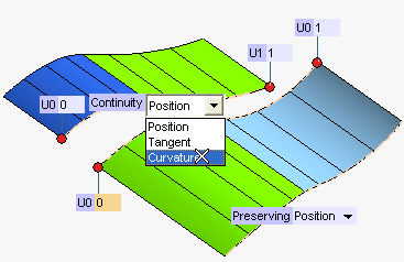
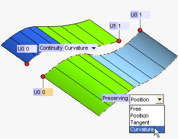
- The Continuity drop-down lists enable you to select the type of continuity to be applied along the selected contours (reference and to be modified) and along the contour marked as Preserving.
The available types are the following (for a detailed description of the continuity types, see Continuity Types):
 ) button to get a preview of the result.
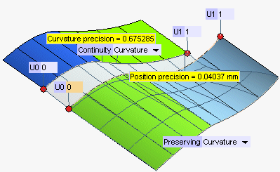
The Bulge factor of the resulting surfaces can be set through the appropriate drop-down list under More Options. The higher the bulge factor, the more rounded the shape of the resulting surfaces (see also "Examples of the Bulge parameter").
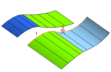
| Number of discontinuities
Please note that when the active parts of the selected contours do not have the same number of tangency discontinuities, a warning is displayed. |
 or
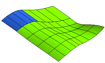
or  to confirm your selections and create the surfaces (the resulting surfaces shown in the illustration below are visible after hiding the original ones).
Click
 to discard your changes.