a. Select Bend from the list.
b. Select Bend and flange from the list.
c. Select Bend and flange chain from the list.
d. Select Rectangular from the list and specify a value in the Gap: edit box.
e. Select Circular from the list and specify a value in the Diameter edit box.
 or
or  to confirm your selections and create the flange.
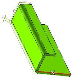
See the circled area in the following images for the difference in flange.
- If you have selected a, you can see the following flange.
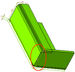
- If you have selected b, you can see the following flange.
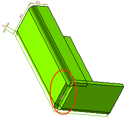
- If you have selected c, you can see the following flange.
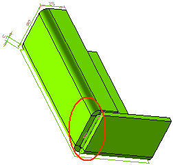
- If you have selected d, the corner relief of the flange will be as formed shown below.

- If you have selected e, the corner relief of the flange with the specified diameter will be formed as shown below.

| Note These reliefs will not appear to be perfectly rectangular or circular when the model is in the bend state. However, exact results are obtained on unbending the model or generating its flat pattern view. |
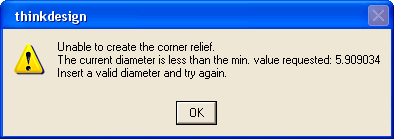
If the specified Diameter (for Circular relief) or Gap: (for Rectangular relief) is less than the minimum possible value, a suitable warning message will be displayed on applying the Flange command.
Click
 to discard your changes.