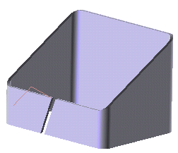
You will create an extruded flange on each of the two edges on the left. As you can see, they are coplanar. After starting the Extruded Flange command, proceed as follows.
To accomplish this task, open file "ExtrFla83.e3".
You will create an extruded flange on each of the two edges on the left. As you can see, they are coplanar.
After starting the Extruded Flange command, proceed as follows.
| 1 | Select the profile that will be used to define the direction of the flange.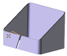
To change the selected profile, right-click on Profile, choose Reset in the context menu and select another profile. |
|
| 2 | In the Type drop-down list select Edges. | |
| 3 | Select each of the edges on which the flanges are to be created. 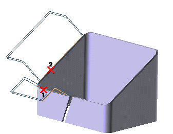 A preview of the corresponding flange is immediately displayed after selecting each edge. To change the selected edges, right-click on Edges, choose Reset in the context menu and perform selection again. When the selected edges are coplanar, as in the case of this example, the Keep Orientation check box under More Options is automatically displayed and selected, in order to maintain the angle between the profile and the plane on which the two selected edges lie, rather than the one between the first edge and the corresponding outer surface. If you prefer the latter condition to be applied, deselect the check box.
|
|
| 4 | Click  or or  to confirm your selections and create the flanges. to confirm your selections and create the flanges.Click  to discard your changes. to discard your changes.
|