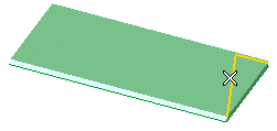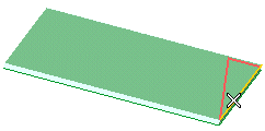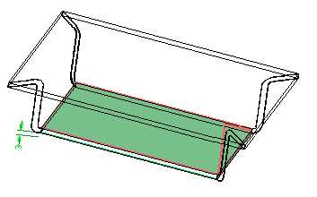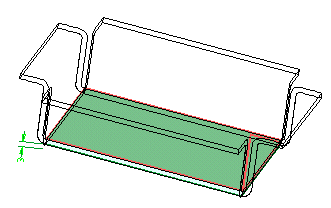
| About the profile
The profile to be selected must:
|
To change the selected profile, right-click on Profile, choose Reset in the context menu and select another profile.

To change the selected edges, right-click on Edges, choose Reset in the context menu and perform selection again.

Deselect Miter to prevent flanges from covering the corners.

 or
or  to confirm your selections and create the flanges.
 to discard your changes.