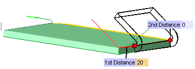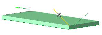
To accomplish this task, open file "ExtFlan01.e3". After starting the Extruded Flange command, proceed as follows.
| 1 | Select the profile that will be used to define the direction of the flange.![]()
To change the selected profile, right-click on Profile, choose Reset in the context menu and select another profile. |
|
| 2 | In the Type drop-down list select Edges. | |
| 3 | Select the edge on which you want to create the flange. ![]() To change the selected edges, right-click on Edges, choose Reset in the context menu and perform selection again. |
|
| 4 | To define the length of the flange, in the Extension drop-down list under More Options select 1st Distance and 2nd Distance. The 1st Distance and 2nd Distance mini-dialog boxes are displayed on the model.
![]() |
|
| 5 | In the 1st Distance mini-dialog box, type the distance of the starting side face of the flange from the first end point of the selected edge. Then hit the TAB key. A preview is displayed.
![]() In the 2nd Distance mini-dialog box, type the distance of the ending side face of the flange from the second end point of the selected edge.
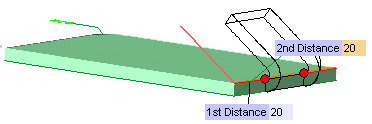
|
|
| 6 | Click or to confirm your selections and create the flange.
![]() Click to discard your changes.
|