
Many improvements have been made in version 2014.1. This document contains a list of short descriptions for each new feature, improvement and enhancement.
The new Along Work Plane check-box has been added to the Analysis Entity Size command.
When selected, it allows to compute the bounding-box in the X, Y and Z directions relative to the current Work Plane. When not selected, the bounding-box is computed in the X, Y and Z directions relative to the World reference system.

Choosing the ANSYS plug-in version
Starting from this version, you can choose whether to install either ANSYS V14.5 or ANSYS V15.0 plug-in from the custom window of the installation wizard during the installation process.
Improvements
In the previous versions of ThinkDesign, all the models imported in ANSYS had Structural Steel as Material.
From the 2014.1 version, instead, the Material associated to a solid in ThinkDesign is taken into account in ANSYS if it exists in ANSYS Material Libraries (name matching).
The correspondence is enabled only if ANSYS Material Properties option is checked-on.
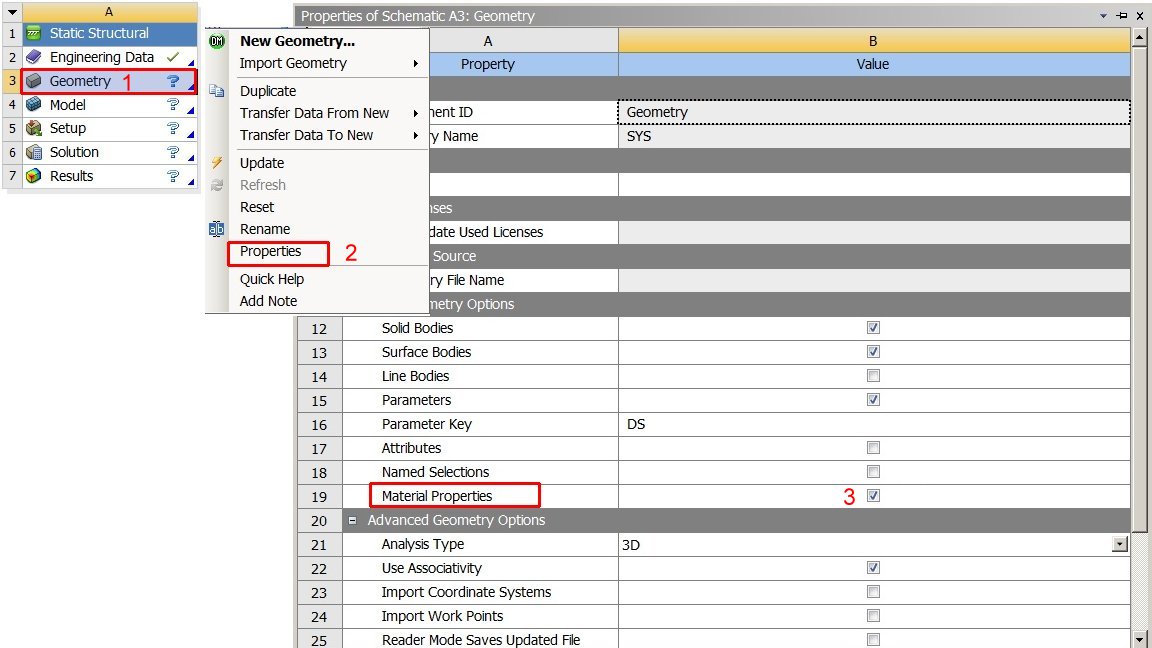
In order to activate the option follow these steps:
| Note Prerequisite of using the ANSYS plug-in is to have the ANSYS application installed in the workstation. |
After setting the Smart Objects and/or Group library path in the Library Path of the System Options dialog box, the new Libraries check box will be selectable in the Configuration Options dialog box of the Configuration ManagerSave command. Selecting it you can share also these settings with the other users.
The TD XchangeReader module is now capable to read:
For the Autodesk® DXF/DWG format, the DWGDirect 3rd party library has been upgraded to Teigha® 3.09 (compatible to library (Autodesk® DWG 2013 file format).
Improvements
A new category Save-Visual Bookmark has been added to the Options dialog box available in Save as Adobe PDF file (*.pdf). The available options have the following meaning.
| View Data | When selected, Visual Bookmarks containing viewport and clipping plane information are exported. When not selected, they are ignored. |
| Hide/Unhide Entities | When selected, Visual Bookmarks containing information on hidden and visible objects are exported. When not selected, they are ignored. |
The User Defined Properties (UDP) assigned to the entire model or to entities are now exported into 3D PDF.
The new information in the PDF are visible in the Model Tree Navigation Panes.
The Mold Standard Parts command has been improved in the selection of the Positioning Points.
After the selection of a positioning points, you can easily add to this selector other points by using the following context menu items:
| TransformMirror about X axis
|
It allows you to add the mirrored points about X of the Work Plane. |
| TransformMirror about Y axis
|
It allows you to add the mirrored points about y of the Work Plane. |
| TransformCopy along X direction
|
Through the Copy of points dialog box, it allows you to add a specific number of points along the X axis at a defined Step Distance |
| TransformCopy along Y direction
|
Through the Copy of points dialog box, it allows you to add a specific number of points along the Y axis at a defined Step Distance. |
| TransformReset Marker Selection |
It allows you to reset the marker selection. For deselecting only one point, you have to click on it by pressing <CTRL>. |
This enhancement allows you to position the standard parts in symmetric points along X or Y or create a pattern of standard parts along X or Y.
In addition the Prevent Rotation by Cutting drop-down list has the new Both sides - oblong option. When it is selected, the profile you get is oblong instead of rectangular.
Multiple separate spacer components instead of one have been implemented in the DME, HASCO and MEUSBURGER catalogs.
In the previous version, when you inserted a Moldbase (DME, Hasco, Meusburger), the Guide pillar had all the same Diameter. In some case it is useful to have three guide pillar with same diameter and the 4th with another diameter. In order to allow this choice the new 3 + 1 option for Leader Pin Top Shank and Leader pin busings has been added to the Guide Elements tab of the DME and MEUSBURGER catalogs.
If the 3+1 option is No, all the four leader pins have same diameter. If it is Yes, three leader pins have same diameter and the 4th has a lesser diameter. The 4th leader pin will be placed at lower right of top view.
In order to access the new features in the DME, HASCO and MEUSBURGER catalogs you have to import the ones available in the 2014.1 version.
The Part List Editor has been improved for the MoldDesign user.
You can configure whether the column in the dialog box is editable or read only.
You can automatically calculate the size (bounding box) of a component and include it in the Part List.
See below for the details.
The PARTSolutions Plug-in has been updated to support the v. 9.04 of Cadenas PARTsolutions.
The Part List Editor contains two extra columns, which show the COMPONENT NAME and the HIERARCHY LEVEL of the component in the assembly. These columns are fixed and not editable, moreover they are not considered when you Export to CSV.
Another important feature is the presence of the Hide entities and the Unhide entities commands in the context menu along with the Zoom Entities command; after selecting a component, they can hide/unhide the selected entities to allow you a better visualization of your model.
The new Editable Property check box allows to configure whether the column in the Part List Editor dialog box is editable or read only.
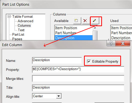
The editable columns have a white background, the others are grayed out.
Two new properties have been added among the ones available in the list of columns in the Table Format - Columns category of the Part List Options dialog box:
| CompSizeAuto | It is a checkbox in part list editor and determines whether the size has to be automatically calculated. When selected, the program automatically calculates the size of the component; the content of the corresponding field of the CompSize column is not editable. When cleared, the string in the corresponding field of the CompSize column is editable. By default the check box is selected. |
| CompSize | It is a string like 142L x 82W x 17H (length x width x height). The automatic value is the bounding-box of the component with respect to the axis of the component itself. |
In this version several improvements have been made to increase the performance of ThinkDesign graphical feedbacks.
When switching between model and drawing environment the visualization of the graphical items, like toolbars, is faster.
The time of displaying the command selection list has been significantly reduced.
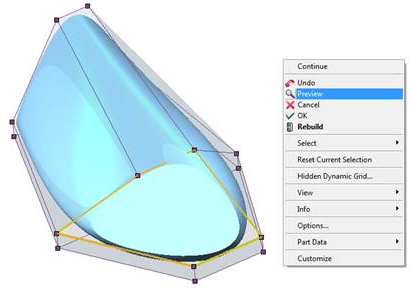
The Subdivision Solid command has been improved, in terms of usability and functionality. First of all it has been provided with a new user interface, that is more intuitive, ergonomic and efficient.
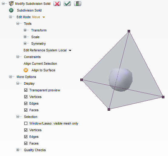
New and simpler selection methods have been developed by introducing the standard use off markers. When the mouse is placed over a face, edge or vertex, it is highlighted in the default thinkdesing mouse-over color (namely red). When the marker is clicked upon, it is highlighted (in orange by default) and selected. Holding the <CTRL> key and clicking on an item will deselect it if it was in the selection, otherwise it will add it to the current selection. Window and Lasso selection are also enabled. Furthermore, whenever a current selection is available, an item is added to the context menu (accessed by right-clicking anywhere in the drawing area) called Reset Current Selection, so as to enable you to empty the current selection.
Edit Mode Changes
Split face, Remove face and Subdivide face modes remain unchanged apart from the selection being made directly onto the face markers. Move and Extrude face modes have been modified and a new Add face mode appears in the drop-down list.
Move
For move operations, there remains only one mode (compared to the 3 in the previous version) in which any selected markers can:
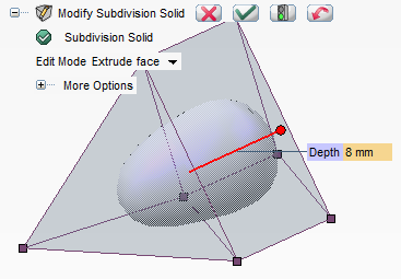
Input or in System OptionsInputMouse Input)Extrude face - Depth Handle
Extrude face has been enhanced with a depth handle for the user to control the length at which the extrusion is made. Simply select the face to extrude and the handle will appear at the default length (that which was previously used). The handle can then be dragged or the depth can be entered manually to get the desired shape. Do note that as before, if during the extrude operation two faces coincide exactly, that is their vertices match, the faces will be destroyed and the shape fused on these vertices.
Add face
A new edit mode is nowe available to add a face. It is a counterpart to the Remove face mode. If the selection of edges is valid, the standard preview button appears at the top of the selection list. When this is clicked, the corresponding face will be built and the underlying solid updated. Do note that the added face will be the smallest possible given the selection as illustrated below.
More Options
This menu is shared by every mode. It contains utilities for the selection and display of markers and Quality Check for the subdivision solid surfaces. This last one remains unchanged from the previous version.
The Windows 8.1 Operating System is now supported on the standard PC platforms.
The think3 Wizards (used in the API-COM environment) is now available for Microsoft Visual Studio 2013.