The Plane on Mesh command enables you to create reference planes, unconstrained planes characterized by its normal direction and root point.
In Reshape a plane can be created with no constraints or with a Parallel to plane constraint. In the latter case, the reference plane can be determined in several different ways.
Insert a Plane on Mesh without constraints
- Select the mesh to insert a plane.
To reset the mesh selection, right-click on Mesh in the selection list, choose the Reset option in the context menu and then select the mesh again.
- Select two or more points the plane should pass through. Select the Selection through check box to select all the nodes in the selection window, by default only the visible nodes will be selected.
- Under the Results node in the selection list, the fitting results shows how accurate the plane creation has been with the inserted values:
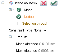
| Mean distance |
represents the average deviation from the mesh surface |
| Max. distance |
represents the maximum deviation from the mesh surface |
- Click the OK button
 to confirm the operation and exit the procedure, or the Apply button
  to apply the operation, or the Cancel button
  to abort.
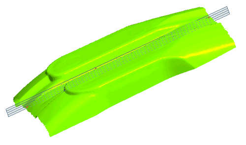 |
| Insert a plane defined by picking points - no constraints |
Insert a Plane on Mesh with a Parallel to plane constraint
The Parallel to plane constraint as selected in Reference plane can be defined in several ways:
3 Points definition of reference plane

- Select the 3 points option in the Reference plane drop-down list.
- Select 3 points on the mesh that defines the plane.
- Select the Angle check box to to enter the plane's angle in degree.
Select the Plane

- Select the Plane option in the Reference plane drop-down list.
- Select the plane you would like to use as a reference for the plane creation.
- Select the Angle check box to to enter the plane's angle in degree.
Perpendicular to axis & through point
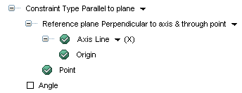
- Select the Perpendicular to axis & through point option in the Reference plane drop-down list.
- Make additional selections for:
| Axis - Line |
This kind of selection implies choosing a construction vector from the model for building the reference plane. |
| Axis - 2 Points |
This kind of selection implies picking 2 points that defines the guiding line for building the reference plane. |
| Axis - X, Y, Z |
Choosing one of the principal axes will use X, Y or Z axis to build the reference plane. |
| 2 points |
The passing point of the reference plane to be created. |
| Select the Angle |
Check this box to enter the plane's angle in degree. |
-
Through axis & point
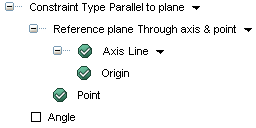
- Select the Through axis & point option in the Reference plane drop-down list.
- Make additional selections for:
| Axis - Line |
This kind of selection implies choosing a construction vector from the model for building the reference plane. |
| Axis - 2 points |
This kind of selection implies picking 2 points that defines the guiding line for building the reference plane. |
| Point |
The passing point of the reference plane to be created. |
| Angle |
Check this box to enter the plane's angle in degree. |
-
On Face

- Select the On Face option in the Reference plane drop-down list.
- Select a face in the model to use as a reference plane.
- Select the Angle check box to to enter the plane's angle in degree.
-
Coefficients

- Select the Coefficients option in the Reference plane drop-down list.
- Select a point for creating the reference plane; coefficient values are displayed.

Insert the coefficient values in order to create the plane, the coefficients govern the mathematic equation Ax+By+Cz+D = 0
- Select the Angle check box to enter the plane's angle in degree.
Bounded

- Select the Bounded option in the Reference plane drop-down list.
- Select a chain of curves to create the reference plane.
- Select the Angle check box to enter the plane's angle in degree.
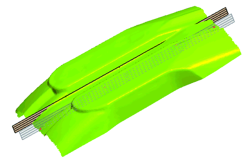 |
| Insert a plane defined by a parallel plane and points picked |


 Insert
 Plane on Mesh
 to confirm the operation and exit the procedure, or the Apply button
  to apply the operation, or the Cancel button
  to abort.


